
1.0 OBJECTIVE: To design, engineer, and supply of Electric Stacker (Model: Modal name) and provide assurance that the machine is manufactured as per the URS and complies with CE recommendations.
2.0 SCOPE: The scope of this qualification document is limited to the Design Qualification of the Electric Stacker (Model: Modal name) for “Company Name and Address”. This qualification document is part of a Validation activity for the Electric Stacker ( Model: Modal name).
The equipment shall be used In-plant for stacking palletized load at specified lift height. The equipment shall operate where the floor is even and has sufficient load-bearing capacity. The gradient of the floor on which the equipment can operate with a full load is 8% and without load is 15%. The equipment can operate at a maximum ambient temperature of 60°C.
3.0 RESPONSIBILITIES:
Client: a) To provide the URS for the equipment.
b) To perform the Factory Acceptance Test (FAT) at the manufacturer’s and
client’s sites.
c) To adhere to Safety Instructions and Preventive Maintenance activities as specified in the DQ Sheets and Operation and Instruction Manuals.
Manufacturer: a) To design, engineer, and provide the complete technical details of the
equipment about its design qualification viz.
(i) To facilitate the client for machine overview,
(ii) To facilitate the client for specifications of the sub-components/bought-out items, and their make, model & quantity, and backup records/ brochures,
(iii) Material of construction of all components
(iv) Brief process description
(v) Safety features and alarms
(vi) Pre-installation requirements
b) To facilitate the client for the Factory Acceptance Test of the machine at their works/ site.
c) To confirm the safe delivery of the equipment to the user site.
d) To ensure that no unauthorized and/or unrecorded design modifications shall take place. If at any point in time, any change is desired in the mutually agreed design, the Change control procedure shall be followed and documented.
e) To ensure the proper installation and commissioning of the equipment.
Related: Design Qualification Protocol for Vertical Laminar Reverse Flow
4.0 USER REQUIREMENTS SPECIFICATION (URS):
| DESCRIPTION | SPECIFICATIONS |
| Equipment | Electric Stacker |
| Capacity | 1500 Kgs. |
| Capacity @ max. Ht. | 850 Kgs. |
| Lift Height | 6000 mm. |
| Height Mast Lowered | 2755 mm. |
| Height Mast extended | 6525 mm. |
| Free Lift | 2235 mm |
| Fork length | 1150 mm X 560 mm. |
| Fork Shut Height | 90 mm. |
| Turning Radius | 1640 mm. |
| Battery | 24V 330 Ah |
| Wheels | Polyurethane |
| Model | ST15 SSFFTL |
| Total Electrical Loads | 1.5 K.W – For Drive Motor 2.0 K.W – For Power Pack |
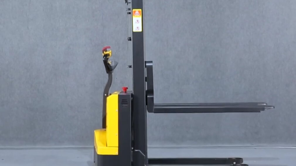
5.0 MACHINE DESCRIPTION:
MAINI makes Electric Stacker versatile equipment that is useful in almost all industrial work environments. It is used for high-intensive stacking and transporting in minimum cycle times. The complete machine can be divided into the following subsections:
a) Chassis Assembly.
b) Mast Assembly.
c) Carriage Assembly.
d) Load & Support Wheel Unit.
e) Suspension and Drive Unit
f) Hydraulic System
g) Electrical System
h) Hoods & Panels.
6.0 TECHNICAL SPECIFICATIONS:
6.1 Overall:
| Sr. No. | Description | Specification |
| 1. | Make | MAINI |
| 2. | Model | Modal Name |
| 3. | Type | Battery Operated |
| 4. | Basic Capacity | 1500 Kgs. |
| 5. | Overall Length | 2215 mm |
| 6. | Overall Width | 850 / 1500 mm |
| 7. | Overall Height | 2755 mm |
| 8. | Overall Weight | 1280 Kg. |
6.2 Mast Program
| Sr. No. | Description | Specification |
| 1. | Raised Mast Height | 6525 mm |
| 2. | Closed Mast Height | 2755mm |
| 3. | Lift Height | 6000 mm |
| 4. | Load Capacity | 850 Kgs. |
6.3 Speed:
a) Travel Speed:
With Load – 5.0 Km/h (Maximum)
Without Load – 6.5 Km/h (Maximum)
b) Lift Speed :
With Load – 0.07 Km/h (Maximum)
Without load – 0.11 Km/h (Maximum)
c) Lowering Speed:
With Load – 0.25 Km/h (Maximum)
Without Load – 0.10 Km/h (Maximum)
6.3.1 Gradient
Laden – 8%
Unladen – 15%
6.4 Fork Dimensions
a) Overall Length – 1150 mm
b) Overall width – 560 mm
c) Lowered Height – 90 mm
5.1 Technical Span of Sub-Assemblies:
| Sr. No | Description | Unit Quantity | Make |
| 1 | Chassis | 01 | — |
| 2. | Mast Assembly | 01 | — |
| 3. | Carriage | 01 | — |
| 4. | Load Wheel | 04 | Speciality Urathane |
| 5. | Support Wheel | 02 | Speciality Urathane |
| 6. | Drive Wheel | 01 | Speciality Urathane |
| 7. | Suspension Casting | 01 | S G Iron Casting |
| 8. | Drive Unit Rating – 1.5 K.W. Series | 01 | CFR, Italy |
| 9. | Hydraulic System Pump Motor Rating – 2K.W | 01 | Haldex, Sweden |
| 10 | Electrical System: | — | — |
| Controller Rating | 01 | Curtis, USA, 24V.250 A Series | |
| Relays Rating | 01 | Albright, U.K 24 V. | |
| Fuse Rating | 01 set | Germany, 100 amps. | |
| Emergency Switches Rating | 01 | Albright, U.K, 24 V | |
| Battery Rating | 01 | Exide finds. 24 V. 330 Ah Traction | |
| Type Charger Rating | 01 | Sirius, 24 V 45 A | |
| 11. | Hoods & Panel | 01 set | ABS |
6.6 Material of Construction:
| Sr. No. | Component Description | Material |
| 1 | Chassis | Mild Steel |
| 2. | Mast | Mild Steel |
| 3. | Load Wheel | Polyurethane |
| 4. | Support Wheel | Polyurethane |
| 5. | Drive Wheel | Polyurethane |
| 6. | Axils & Pins | Mild Steel |
| 7 | Suspension unit | Grey Cast Iron Casting(GG25) |
| 8. | Lift Piston | En8 + HC Plated |
| 9. | Hoods & Panels | ABS |
7.0 SAFETY FEATURES AND ALARMS:
7.1. Horn Switch (H): Provided to caution people or other vehicles when driving and negotiating comers.
7.2. Safety reverse button (F): The purpose of this button is to secure the operator against being squeezed between the tiller arm and a wall, a rack, or any other obstacle.
7.3. Emergency Power Cut–Off Switch (A): This is pushed down to quickly cut off the entire power supply to the equipment. Should be used in the event of unintentional movements or in case of fire, short circuit, etc. during operation.
8.00 FAT PROCEDURE:
8.1 Study the work order before inspecting the equipment. Clarification if any, clarify
with Marketing and PPC departments.
8.2. Dimensional:- (Record all the dimensions by measuring tape)
a) Check the minimum height (fork height) of the equipment and record (Ground to fork top level)
b) Check the fork width & length.
c) Switch on the key and emergency switch. Operate the side stabilizer level and then operate the main cylinder lever.
d) Lift the carriage up to maximum height and note down height (ground to fork top level laden/unladen)
8.3 Visual Inspection:-
a) See the primary cylinder is lifting first and the movement of the hose is satisfactory.
b) i) See the roller contact, Is it having contact with mast inner surface? (see the gap in the SS roller. The gap should be max. 2mm).
ii) See the roller contact. Is it having contact with mast inner side surface?
iii) Check the support wheels and load wheel’s movement/contact, with and without load.
b) See the deflection of the mast (laden) at the maximum height.
c) Check aesthetic aspects. (welded joints, assembly fitment, uniform bolt, nut, and washer used.)
d) Check for the painting (non-coverage, Scratch)
e) See the cover fitment and the gap. It should be more than a 2 to 3 mm gap. Check for the leakage if any, (at oil seals and welded joints)
8.4 Load Test:
a) Test the equipment without load and with the load. (As specified in a work order or refer to Catalogue). For without load lift the carriage with the help of a lever. Parallelly switch on the stopwatch and record. Lower the carriage in the same way and record. Repeat the same for with load.
8.5 Performance Test:-
a) Lift the carriage up to a certain height and lower. Verify the carriage is lifting and roller movement is perfect.
b) Move the equipment forward and reverse. Parallelly apply the brakes immediately and see the effect.
c) To check or shrinkage of the cylinder, observe the carriage movement when the carriage is in a static position for 2 minutes (check shrinkage with load also).
d) See the electrical connections and their routing is perfect.
e) Move the equipment in reverse direction with the help of butterfly switch and hit the safety switch in the stomach, the equipment has to move forward. See the effect.
8.6 Sub Assembly:-
a) Note down the details of the sub-assembly part used. Example:- Drive motor, Pump Motor, Lift Cylinder, Battery, relay, Controller, Safety Socket, Valves, and Charger.
8.7 Pre-dispatch check:-
a) See the painting finish, Cover fitment and all electrical connections are functioning.
b) Attachment if any, see the functional aspect and record the same.
c) If any rework, information has to go to the assembly department with the rework record.
d) Verify the equipment once again after the rework, if found satisfactory in all respect, give the clearance for dispatch/customer inspection.
9.0 APPENDIX for Design Qualification of Electric Stacker:
9.1 List Of Abbreviations
KW: Kilowatt
V: Volt
Ah: Ampere Hour
DQ: Design Qualification
URS: User Requirement Specification
FAT: Factory Acceptance Test
9.2 Reference Documents for Design Qualification of Electric Stacker:
9.2.1 Manufactures Brochure (s) / Manual (s):
a) Instruction/maintenance manual/spare part list
b) Final Inspection Report
c) Factory Acceptance Test Report
d) Test Certificates.
9.2.2 Client’s Purchase Order:
9.2.1 and 9.2.2 To be submitted as the finalization and execution of the order progresses.

Naresh Bhakar is the Founder and Author at Pharmaguddu.com, bringing his extensive expertise in the field of pharmaceuticals to readers worldwide. He has experience in Pharma manufacturing and has worked with top Pharmaceuticals. He has rich knowledge and provides valuable insights and data through his articles and content on Pharmaguddu.com. For further inquiries or collaborations, please don’t hesitate to reach out via email at [email protected].