Home » Qualification » Installation Qualification of Sterilizing and Depyrogenation Tunnel (Protocol)
Installation Qualification of Sterilizing and Depyrogenation Tunnel (Protocol)
Installation Qualification of Sterilizing and Depyrogenation Tunnel is done to ensure that the Sterilizing and depyrogenating tunnel system received matches the Design specification and also to ensure that it is properly and safely installed.
Equipment Name:
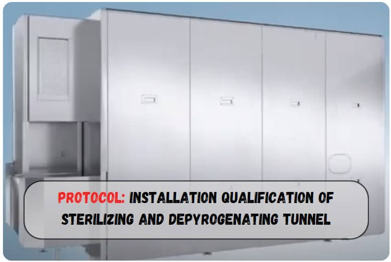
Steripack Sterilizing and Depyrogenation Tunnel
Equipment No.:
EQI/XX/XXX/01
Protocol Reference No.
—
Report No.
—
SERIAL NO.
ITEM DESCRIPTION
1.0
PROTOCOL APPROVAL
2.0
OVERVIEW:
2.1
Objective
2.2
Purpose
2.3
Scope
2.4
Responsibility
2.5
Execution Team
3.0
ACCEPTANCE CRITERIA
4.0
REVALIDATION CRITERIA
5.0
INSTALLATION QUALIFICATION PROCEDURE
5.1
System Description
5.2
Instruction For Filling The Checklist
5.3
Installation Checklist
5.4
Identification Of Major Components
5.5
Verification of material of construction
5.6
Identification Of Supporting Utilities
5.7
Identification Of Control And Safety Devices
5.8
Identification of Standard operating procedure (SOP)
5.9
Identification Of Component to be calibrated
5.10
Verification Of Drawings and Documents
5.11
Abbreviations
5.12
Deficiency And Corrective Action(s) report(s)
5.13
Annexure(s)
6.0
INSTALLATION QUALIFICATION FINAL REPORT
6.1
Summary
6.2
Conclusion
6.3
Final report approval
1.0
PROTOCOL APPROVAL:
The signing of this approval page of the Protocol indicates agreement with the qualification approach described in this document. If a modification to the qualification approach becomes necessary, an addendum shall be prepared and approved. The protocol cannot be used for execution unless approved by the following authorities.
This Installation Qualification protocol of Sterilizing and Depyrogenation Tunnel. Has been reviewed and approved by the following persons:
The objective of developing and executing this protocol is to collect sufficient data pertaining to the Sterilizing and depyrogenating tunnel and define the qualification requirements and acceptance criteria for the Sterilizing and depyrogenating tunnel. Successful completion of these qualification requirements will provide assurance that the Sterilizing and depyrogenating tunnel was installed as required in the Injection area.
2.2
PURPOSE:
The purpose of this protocol is to establish documentary evidence to ensure that the Sterilizing and depyrogenating tunnel system received matches the Design specification and also to ensure that it is properly and safely installed. The Sterilizing and depyrogenating tunnel is used for sterilizing and depyrogenating of free-standing vials having a height of less than 100mm using the laminar air flow principle and the short-time sterilization method. The equipment shall operate under a dust-free environment and conditions as per the GMP requirements.
2.3
SCOPE:
This Protocol is applicable to the installation of a Sterilizing and Depyrogenation Tunnel at the sterile injectable manufacturing facility in XYZ Pharmaceutical.
2.4
RESPONSIBILITY:
Mention responsible person and Their Department.
2.5
EXECUTION TEAM:
The satisfactory installation of the Sterilizing and depyrogenating tunnel shall be verified by executing the qualification studies described in this protocol. The successfully executed protocol documents that the Sterilizing and depyrogenating tunnel is installed and is satisfactorily integrated. The execution team is responsible for the execution of the installation of the Sterilizing and depyrogenating tunnel. The execution team comprises of:
DEPARTMENT
DESIGNATION
NAME
SIGNATURE
DATE
PROJECTS / ENGINEERING
PRODUCTION
QUALITY ASSURANCE
3.0
ACCEPTANCE CRITERIA:
3.1
The Sterilizing and Depyrogenation Tunnel shall meet the system description given in the design qualification.
3.2
The Sterilizing and depyrogenating tunnel shall meet with the acceptance criteria mentioned under the topic “Identification of major components”.
3.3
Material of construction compiles with test certificate.
3.4
The Sterilizing and depyrogenating tunnel system shall be operated by manual /PLC.
4.0
REVALIDATION CRITERIA:
The Sterilizing and depyrogenating tunnel has to be revalidated if:
💡There are any major changes in system components which affect the performance of the system. 💡After major breakdown maintenance is carried out. 💡Shifting of the equipment from one location to another. 💡Any Major modification in the existing equipment/line. 💡As per the revalidation date and schedule.
5.0
INSTALLATION QUALIFICATION PROCEDURE:
5.1
SYSTEM DESCRIPTION:
Sterilizing and depyrogenating tunnel enables the integration of the process of sterilization and depyrogenation of washed empty vials for sterile, continuous automatic sterilizing in which all steps are performed under class 100 conditions.
The Tunnel is comprised of four zones, i.e. Drying zone, sterilizing zone, cooling zone, and Stabilizing zone.
Drying, cooling, and stabilizing zones are essentially once-pass-through Laminar flow units comprising as standard features, Pre-filters, motor blower assembly, and HEPA filters.
Extract and exhaust blowers are provided under the conveyor connected to the ambient using a common duct.
A stainless steel Wire Loop conveyor transfers vials through drying, sterilizing, cooling, and stabilizing zones under non-turbulent class 100 fresh air.
Container-controlled partition wall adjustment panels are provided at the entry and exit of the sterilizing zone.
In the Infeed area air taken from the room is prefiltered and aspirated by a blower through a HEPA filter. A laminar flow of air is sent vertically down onto the containers.
Containers passed in the drying zone they are preheated up to 90-110°C by the hot air bleeding out of the sterilizing zone. the air along with water vapor is picked up underneath of the conveyor belt by the extract blower and ejected to the outside.
Dried containers are moved over to the sterilizing zone. The sterilizing zone mainly comprises of resistance heating elements, HEPA filters, and temperature-regulating devices.
Hot filtered air is re-circulated in the sterilization zone, which sweeps the containers from top to bottom.
Differences exist in the hot air temperature and conveyor speed settings depending on the total mass of the glass required to be sterilized and cooled.
Equal pressure drop across the filter enables in creation of an extremely even distribution of air circulation.
This uniformly distributed hot air sterilizes and depyrogenates the containers. In the cooling and stabilization zones, containers are subjected to a Laminar flow of HEPA-filtered air taken from the room.
The airflow is profiled in such a way that the glass temperature as it excited the sterilizing zone would be transitioned at a nearly linear rate.
Stabilizing zone is used as a transition area separating the critical filling area and washing area.
Conveyor system is controlled by the container accumulation at the infeed and the set temperature for the conveyor starts.
SS wire Loop conveyor is driven by a gear motor with an AC frequency-controlled drive and tension roller for maintaining the correct tension of the conveyor belt.
Control and recording systems for the parameters governing the sterilizing process such as air temperature, belt speed, and holding time are standard features.
Sterilizing and depyrogenating tunnel is equipped and controlled with an Allen Bradley PLC and MMI (Man Machine Interface) which in conjunction with RTDs, Infeed / Outfeed Proximity switches, Dot Matrix printers, and Allen Bradley frequency converter (Variable speed drive) make the operations fully automatic.
Mode of operation enables to opt a) Auto mode b) Semi-auto mode c) Maintenance mode.
In the Auto mode, the operation of the tunnel is fully automatic. The tunnel starts and stops at a predetermined time. All blowers are running continuously except the sterilizing zone turbine, which cuts off when the temperature reaches 90°C.
Tunnel can be operated manually and automatically in Semi-auto mode.
In the Maintenance mode, all operations are being done manually.
5.2
INSTRUCTION FOR FILLING THE CHECKLIST:
5.2.1
In case of compliance of the test use the word ‘Complies’ otherwise use ‘Does not comply‘ to indicate non-compliance.
5.2.2
For identification of the components of the equipment and utilities use the word ‘’yes’’ to show its presence and use ‘No’ to indicate the absence of the identity
5.2.3
Give detailed information in the summary and conclusion part of the Installation Qualification report.
5.2.4
Whichever column is blank or not used ‘NA’ shall be used.
5.3
INSTALLATION CHECKLIST:
The installation checklist is as follows:
Sr. NO.
STATEMENT
YES / NO
CHECKED BY(SIGN)
DATE
Verify that the “As Built” drawing is complete and represents the design concept.
Verify that major components are securely anchored and shockproof.
Verify that there is no observable physical damage.
Verify that there is sufficient room provided for servicing.
All-access ports are examined and cleared of any debris.
Equipment identification nameplate visible.
Verify that all piping and electrical connections are done according to the drawings.
Safe electrical connections.
A wiring diagram affixed to the inside section of the control panel.
Units installed on the foundation are secure in place as per the manufacturer’s recommendations.
Check the dimensions: 3960 mm (L) X 1525mm (W) X 2340mm(H)
5.4
IDENTIFICATION OF MAJOR COMPONENTS:
Describe each critical component and check them and fill out the inspection checklist.
System components
Design Specifications
Complies / does not comply
Checked By (Sign.)
Date
Equipment description
Name: Steripak sterilizing and depyrogenating tunnel, Make:Teknopak, Model: V – 900 H2 C3, Output: 150 vials/minute of 5 ml to 30 ml vials.
HEPA Filter modules for drying, sterilizing, cooling and stabilizing zone
SS 304
Visually with test certificate
2
HEPA Filter protective grills above the conveyor
SS 304
Visually with test certificate
3
Side panels covering the conveyor sides from grills to conveyor
SS 304
Visually with test certificate
4
Loop conveyor
SS 304
Visually with test certificate
5
External panels covering the base frame and hot zone
SS 304
Visually with test certificate
6
Control panel
SS 304
Visually with test certificate
7
Tray below conveyor
SS 304
Visually with test certificate
8
Diaphragm
SS 304
Visually with test certificate
5.6
IDENTIFICATION OF SUPPORTING UTILITIES:
Sr. No.
UTILITY
PROPERLY IDENTIFIED & CONNECTED (YES/NO)
CHECKED BY (SIGN)
DATE
1.
Electrical supply415 V, 3 Phase, 50Hz
5.7
IDENTIFICATION OF SAFETY DEVICES:
Identify and record the safety features (if any) and their function in the following tables:
Sr.No.
Safety Devices Description
Specified function
Identified by(Sign.)
Date
1.
Control Panel And Man Machine Inter Face
Check the control panel and the man-machine interface is installed without any damage.
2.
Check the keyboards
The keyboard should be as per the diagram.
3.
Check the electric circuit of the machine
The electric circuit should be as per the circuit diagram given in the manual.
4.
Check for the overload safety devices
The electric circuit should be provided with a miniature circuit breaker.
5.
Check for Earth connection
Earth connection should be provided.
5.8
IDENTIFICATION OF STANDARD OPERATING PROCEDURE (SOP)
The following Standard Operating Procedures were identified as important for the effective performance of the Steripack Sterilizing and Depyrogenation Tunnel.
1.
Operation and cleaning of Steripack Sterilizing and depyrogenating Tunnel.
2.
Preventive maintenance of Steripack Sterilizing and depyrogenating Tunnel.
The following documents are reviewed and attached as listed below:
Sr. No.
DRAWING AND DOCUMENT DETAIL
CHECKED BY (SIGN)
DATE
5.11
ABBREVIATIONS
Following Abbreviations are used in the installation qualification protocol of Steam sterilizer cum bung processor. QA – Quality Assurance M.O.C – Material of construction SS – Stainless Steel RPM – Revolutions per minute SOP – Standard Operating Procedure HOD – Head Of Department PLC – Programmable Logic Controller MMI – Man Machine Interface SDT – Sterilizing and depyrogenating tunnel
5.12
DEFICIENCY AND CORRECTIVE ACTION(S) REPORT(S)
The following deficiency was identified and corrective actions were taken in consultation with the validation team.
Description of deficiency:
Corrective action(s) taken:
5.13 Annexure(s):
Sr.No.
Annexure No.
Title of Annexure
6.0
INSTALLATION QUALIFICATION FINAL REPORT:
All the IQ data sheets and discrepancy reports shall be reviewed by the validation team to prepare a summary report. The summary of IQ shall be used to draw conclusion for approval of the installation qualification report.
6.1
SUMMARY
6.2
CONCLUSION
6.3FINAL REPORT APPROVAL
It has been confirmed that all tests required by the Sterilizing and Depyrogenating Tunnel protocol have been completed, reconciled, and attached to this protocol or included in the qualification summary report. It has been confirmed that all amendments and discrepancies are documented, approved, and attached to this protocol.
The signature in the block below indicates that all items in this qualification report for the Sterilizing and Depyrogenating Tunnel have been reviewed and found to be acceptable and that all variations or discrepancies have been satisfactorily resolved.
Naresh Bhakar is the Founder and Author at Pharmaguddu.com, bringing his extensive expertise in the field of pharmaceuticals to readers worldwide. He has exprience in Pharma manufactring and worked with top Pharmaceuticals. He has rich knowledge and provides valuable insights and data through his articles and content on Pharmaguddu.com. For further inquiries or collaborations, please don't hesitate to reach out via email at [email protected].