
Learn About the scope, responsibility, objective, acceptance criteria, Technical specification, Drawing, Checklist, Calibration, and Documents required for the Design Qualification Protocol of Purified Water Storage & Distribution System.
DESIGN QUALIFICATION:
| NAME OF THE UTILITY / EQUIPMENT /SYSTEM / AREA | Purified water Storage & Distribution System |
| VENDOR’S NAME & ADDRESS | — |
| USER DEPARTMENT | XYZ Pharmaceuticals |
| DOCUMENT NUMBER | XYZ |
TABLE OF CONTENTS:
| S.N. | STAGE |
| 1 | OBJECTIVE & SCOPE |
| 2 | ACCEPTANCE CRITERIA |
| 3 | RESPONSIBILITIES |
| 4 | SYSTEM DESCRIPTION |
| 5 | BASIS OF DESIGN AND ASSUMPTION |
| 6 | TECHNICAL SPECIFICATION |
| 6.01 | STORAGE TANK |
| 6.02 | DISTRIBUTION PUMP |
| 6.03 | VENT FILTER |
| 6.04 | SANITARY PRESSURE GAUGE |
| 6.05 | TUBES AND FITTINGS |
| 6.06 | COMPOUND PRESSURE GAUGE |
| 6.07 | TEMPERATURE SENSOR |
| 6.08 | TEMPERATURE INDICATOR CUM CONTROLLER |
| 6.09 | CONDUCTIVITY SENSOR |
| 6.10 | CONDUCTIVITY INDICATOR CUM CONTROLLER |
| 6.11 | DIAPHRAGM VALVE |
| 6.12 | STEAM CONTROL VALVE |
| 6.13 | LEVEL TRANSMITTER |
| 6.14 | FLOW METER |
| 6.15 | 3 WAY DIVERTOR VALVE (DUMPING) |
| 6.16 | ULTRA VIOLET PURIFIER |
| 6.17 | SHELL & TUBE HEAT EXCHANGER |
| 6.18 | CONTROL PANEL |
| 7 | DRAWINGS REQUIRED |
| 8 | CALIBRATION OF INSTRUMENTS |
| 9 | SUPPORTING UTILITIES |
| 10 | PRE-QUALIFICATION CHECKLIST |
| 11 | DOCUMENTS REQUIRED |
| 12 | DESIGN QUALIFICATION REPORT APPROVAL |
1.0 OBJECTIVE AND SCOPE
1.1 Objective:
A) To prepare detailed specifications for all major components of Equipment/ instruments to ensure that the User Requirement Specifications are Achieved.
B) To design the equipment/instrument in conjunction with the design data in order to provide a basis for the vendor, manufacturer & / or design engineer to design the system when the project begins.
1.2 Scope:
Application to any equipment, system, facility, process, or software program.
a) When subjected to new installation
b) When the existing system is replaced with the new system.
c) When the existing system is subjected to up-gradation & / or modification.
d) When the existing system is relocated to another position
All URS shall be defined by the user department in consultation with the engineering department, which should be finalized and mutually discussed with the system supplier, vendor & or manufacturer.
2.0 Acceptance Criteria:
2.1 Equipment/ Utility system shall conform to specifications which are as per the user requirements.
2.2 The Equipment / Utility/system shall conform to the predetermined requirements and a certificate is issued by the projects / Engineering Department.
2.3 The following points are included in the design:
- Water quality is to be maintained as per the input feed quality at the user points.
- Gradient 1:100 to 1:200 for complete drainability.
- Velocity @ 2.2 m/s during non-peak load hours.
- Dead legs if any shall be <=3 D
- POU Pressure – 1.0 Kg/cm2
- Loop circulation Temp maintained at ambient temperature.
- Chloride free Insulation if any:
- The system is CIP / SIP – for the storage tank and distribution loop
- Orbital Weld Joints and Sanitary Tri-clamp joints
All contact parts (Material of construction) are as below–
3.0 Responsibilities:
- User Dept.: For providing user requirements (Technical and CGMP)
- Engineering: To review the specifications from installation and Maintenance aspects.
- QA: To review the specification from GMP Aspects
- Vendor: To review and agree upon the requirements.
4.0 System Description:
The Purified water generated shall be transferred to the Purified water storage tank of 2000 Liters (Client’s Scope). This Purified water from the storage tank is then re-circulated in a closed loop to various user points with the following features.
A- The storage tank assembly consists of:
- SS 316L wetted parts, Plain.
- Dished ends at bottom for complete drainability and at top to avoid stagnation.
- The spray ball located at the center nozzle (loop return) on the manhole for continuously wetting all the contact parts on the top surface of the tank including the manhole’s internal surfaces.
- Sanitary nozzles are for feed, re-circulation, vent, pressure gauge, level switch, spare nozzles on the top (manhole), and outlet at the bottom.
- The surface finish is less than 0.5 Ra inside, and the mat finish is on the outside surface.
- Sterile vent filter on the tank top.
B- The distribution pump consists of the following features:
- SS 316 wetted parts
- Mono-block, Centrifugal type
- Sanitary with zero hold-up volume
C- Distribution loop consisting of the following features:
- SS 316L, laser welded Bead removed tubes, Electro-polished.
- Internal surfaces finish less than 0.5 Ra.
- Outside Mirror Polish.
- Installed at a slope of 1:100 for complete drainability.
- Properly supported with SS304 contact parts.
- Dead legs of not more than 3D.
- No hold-up volume in case of shutdown.
- Normal velocity of 2.2 m/s and during peak load velocity of min. 1.2m/s shall be maintained.
- All possible joints shall be orbital welded; the remaining shall be sanitary tri-clamp type.
D- Apart from the above major items, the system has the following features:
- The complete storage and distribution system shall have provision for hot water sanitization by applying steam to the shell of shell and tube heat exchanger in loop supply. The Sanitization process is semi-automatic.
- Have the necessary pressure gauges Viz at the pump outlet, loop return, and Compound pressure gauge on a tank top.
- Conductivity controllers in feed supply & loop supply.
- Temperature sensors in tank and loop return.
- Level controller on a tank for pump controlling and feed control.
- Metal tube flow meter in loop return to monitor flow rate/velocity.
- Auto Dumping valve in loop supply for high conductivity.
- The Back Pressure Valve in the Loop returns to regulate pressure and flow.
- The electrical control panel shall control the complete system.
5. Basic of Design And Assumption:
5.1 Feed Water Sample:
Generation of PURIFIED water shall be as per the USP standards (Client’s scope).
5.2 Product Water Quality:
The product water quality at the point of use (POU) shall comply with PURIFIED water Specifications. Microbial Limits shall be as follows:
| Allowable limit | 100 CFU / ml |
| Acceptable limit | 75 CFU / ml |
| Action limit | 50 CFU / ml |
| Alert limit | 25 CFU / ml |
Assumption: The feed water quality is as per PURIFIED tare Standards.
5.3 Facility Operation:
The plant operation will be for 8-16 hours/day and the PURIFIED water system will re-circulate 24 hours/day to avoid stagnation. The system shall be run at ambient temperature.
5.4 Water Demand at Point of Use:
The system is being designed on the basis of Water Consumption Profile provided by the Customer. The peak load of the loop shall be not more than 1400 LPH at any given time.
5.5 System Pressure and Temperature:
The Purified water re-circulation is designed to deliver PURIFIED water to various user points at a Pressure of 1.5 Kg. /cm2.
5.7 System Sanitization:
The Storage and Distribution system is sanitized at 80-85°C in 45 min cycle. The frequency of hot water sanitization shall be determined during validation but normally would be once every week.
5.8 SKID Mounted / Modular Approach:
The entire system is designed on a modular basis and is skid-mounted so as to facilitate Validation as per current international norms. This means that individual Equipment/Instruments shall be assembled in the factory, which shall reduce site work and will help in ensuring achieving design specifications.
5.9 Control Philosophy:
The complete PURIFIED water system shall be monitored and controlled on a timely basis from a electrical Control panel. This is a semi-automatic control system, that will monitor critical on-line parameters like conductivity, level, and temperature and will not provide data logging.
5.10. cGMP Compliance:
The following points are included in the design:
- Gradient 1:100 to 1:200 for complete trainability.
- Differential Pressure in a loop heat exchanger between stream and process line.
- Velocity @ 2.2 m/s during non-peak load hours.
- POU are Zero dead leg Valves.
- Dead legs<=3 D
- Orbital welded joints wherever possible and Tri-clamp joints.
- Loop circulation Temp maintained at ambient temperature.
- System is CIP / SIP – for the storage tank and distribution loop.
All contact parts (Material of construction) are as below:
Material of Construction:
| Component | Specified |
| 1. Storage Tank | SS 316L |
| 2. Cartridge (0.2) micron) | PTFE |
| 3. Vent Filter Housing | SS 316L |
| 4. Cartridge | PTFE |
| 5. Manual Diaphragm Valve | SS 316 |
| 6. Pressure Gauge | SS 316 |
| 7. Temperature sensing element (thermo well) | SS 316L |
| 8. Level Transmitter | SS 316 / PTFE |
| 9. Actuated control valve | SS 316 |
| 10. Pump | SS 316 |
| 11. Piping | SS 316L |
| 12. Conductivity Sensor | SS 316 |
| 13. UV Housing | SS 316L |
| 14. Gasket | EPDM/PTFE/VITON/SILICON |
Flow statistics:
| Normal flow rate | 3100 LPH (2.2 m/s) |
| Peak load | 1400 LPH |
| Flow rate during peak load | 1700 LPH (1.2 m/s) |
Pressure statistics:
| Loop return pressure (Min. Required) | 1.5 Bar |
| Pressure drop across the loop (Considering 180 mtr. Of length) | 3.7 Bar |
| Pump pressure (Min. Required) | 5.2 Bar |
| Pump Selected | 3500 LPH @ 55MWC |
Temperature statistics:
| Normal temperature | Ambient. |
| Sanitization | >80 deg. Cel. |
Water quality
The water quality at the inlet of the storage tank shall be maintained throughout the storage and distribution system with once-a-week sanitization of the system. However, the period of sanitization shall be determined during validation.
6. Technical Specification:
ANNEXURE A – TECHNICAL SPECIFICATIONS FOR PURIFIED WATER SYSTEM:
6.01 Distribution pump:
| Type | Sanitary, Centrifugal, and Monoblock |
| MOC | SS 316 for contact parts |
| Rating | 5 HP |
| Capacity | 3500 LPH @ 55MWC |
| Make | Make Name |
6.02 Vent filter:
| Type | Code-7, Jacketed |
| Ratings | 0.2 Micron absolute |
| MOC of cartridge | PTFE |
| MOC of Housing | SS316L |
| Size/no. Of element | 10” / 1 |
| Make | Make Name |
6.03 Sanitary Pressure Gauges:
| Type | Sanitary, Chemical seal, Glycerin filled |
| Chemical seal | SS 316 Diaphragm with silicon oil |
| Dial size | 4.0” |
| MOC | SS 316L wetted parts, Rest SS304 |
| Make | Make Name |
| Range | 0 to 10 Kg/cm2 |
6.04 Tubes & Fittings:
| Type | Laser welded, Bead removed, Electro-polished |
| MOC | SS 316L |
| Thickness | 16 Swg |
| Size | 1.0” |
| Internal / External Finish | Less than 0.5 Ra / Mirror Finish |
6.05 Sanitary Compound Pressure Gauges:
| Type | Sanitary, Chemical seal, Glycerin filled |
| Chemical seal | SS 316 Diaphragm with silicon oil |
| Dial size | 4.0” |
| MOC | SS 316L wetted parts, Rest SS 304 |
| Make | Make Name |
| Range | -1 to 5 Kg/cm2 |
6.06 Temperature sensor:
| Make | Make Name |
| Type | PT-100, Simplex |
| MOC | Contact parts of SS 316L |
| Range | 0-150°C |
6.07 Temperature Indicator cum Controller:
| Make | Make Name |
| Type | Display with set points and 4-20mA outputs |
| Supply | 230 VAC |
| Mounting | Panel mounted |
| Model | Model Name |
6.08 Conductivity Sensor:
| Make | Make Name |
| Type | Sanitary |
| End connection | Welded Tri-clamp, SS316L |
| MOC | Contact parts of SS316, PTFE Insulators, Viton ‘O’ ring |
| Max. Temperature | 125 deg. Cel |
| Mounting | Online, flow through |
6.09 Conductivity Indicator cum controller:
| Make | Make Name |
| Inputs | Conductivity sensor |
| Outputs | Relay output |
| Display | 3.5 digits |
| Range | 0-10 mS/cm |
| Temperature compensator | Automatic |
6.10 Diaphragm Valves:
| Make | Make Name |
| Type | Diaphragm |
| MOC Body / Bonnet | SS316L / Epoxy Bonnet |
| Diaphragm | EPDM grade 325 |
| End connection | Tri-clamp |
6.11 Steam ON / OFF Valve:
| Make | Make Name |
| Type | Pneumatic, Single-acting |
| Media type | Plant steam |
| Operating temperature | 150 deg. Cel. |
| End connection | 1 ½” Tri-clover |
| Control action | Normally close, slow opening |
| Valve type | Angular Globe type |
| Valve size | 1.5” |
| Wetted parts | SS304 |
6.12 Level Switch:
| Make | Make Name |
| Type | Magnetic Float type |
| MOC | All contact parts SS316 |
| End connection | Tri-clamp |
| Display | None |
| No. of Floats | Two |
| No. of set points | Four |
| Length | As per tank height |
| Outputs | 4 nos. Relay O/P |
6.13 Flow Meter:
| MAKE | Make Name |
| TYPE | Metal tube rotameter |
| RANGE OF MEASUREMENT | 400 to 4000 LPH |
| PROCESS END CONNECTION | 1.5” TRICLOVER SS 316, |
| WETTED PARTS | SS316 |
6.14 3-WAY Diverter Valve:
| MAKE | Make Name |
| MODEL | 3-way diverter valve |
| TYPE | Pneumatic, Single Acting |
| PROCESS END CONNECTION | Tri-clover SS 316 L welded |
| WETTED PARTS (diaphragm) | SS 316 L |
| SEALING MATERIAL | EPDM |
| APPLICATION STANDARD | Sanitary, Steam Sterilizable |
| TOTAL PORT | 3 nos, Port 1 –inlet, Port2 & 3 – outlets |
6.15 ULTRA Violet Purifier (3000 LPH):
| SERVICE | D.M.WATER / ULTRA FILTERED WATER |
| MODEL NO. | Model Name |
| MAKE | Make Name XYZ |
| MAXIMUM OUTPUT EFFICIENCY | 99.9% |
| MAXIMUM FLOW RANGE | 3000 LTRS/ HR |
| TRANSMITTING MEDIUM | QUARTZ JACKET AROUND EACH LAMP |
| NO.OF HIGH-INTENSITY UV LAMPS | 02 NOS |
| WAVELENGTH OF UV LAMP | 2537-ANGSTROM UNITS OR 254 NM |
| NOMINAL WATTAGE OF THE LAMP | 39W |
| ULTRAVIOLET OUTPUT OF THE LAMP | 13.8W |
| UV DOSAGE | 25000 µ W-s/cm2 |
| LIFE OF THE UV LAMP | 7000 WORKING HOURS |
| VESSEL CONSTRUCTION | SS 316L STAINLESS STEEL VESSEL CONTAINING 2 LAMPS, EACH ENCLOSED IN QUARTZ GLASS WITH SINGLE END STAINLESS STEEL FLANGED END |
| WIPER ASSEMBLY | PROVIDED |
| SUPPLY VOLTAGE | 230 V SINGLE-PHASE |
| INLET/OUTLET CONNECTION | 1.5” TRI-CLOVER ENDS |
| INSTRUMENTATION | RUNNING TIMER METER, UV OPERATING, INDICATOR, INTENSITY METER |
| LAMPS MAKE | Make Name |
| LAMP MODEL | Model Name |
6.16 Shell & Tube Heat Exchanger:
6.17 Control Panel:
| Type | ELECTRICAL, Semi-Automatic |
| Mounting | Wall Mounted |
| Fabrication and Finish | MS Powder coated |
| Capacity | 12 HP, 440V 3 Phase, 5 Wire |
| PLC & HMI | None |
| Power Supplies AC/DC | 440/220 500 VA Isolation Transformer |
| Panel Mounted Instruments | Temperature Ind. Cum Controller – 2 Nos.Conductivity ind. Cum controller – 2 Nos.Level Ind. Cum controller – 1 Nos.Hooter – 1 Nos. |
| Operator Controls/Mimic/AnnunciationAll Switchgear & control push-buttons & Indicator will be L & T make | 1. E Stop Mushroom Push Button2. Control on indication3. R, Y, B Supply indication4. Other controls as listed |
| Instrument Wiring | Shielded Cables, isolated from other wiring with separate grounding bus |
| Termination | Bottom |
7. Drawings Required:
| S. NO | DESCRIPTION | DRAWING NO. | REV. |
| 1 | P & I DIAGRAM FOR PURIFIED WATER SYSTEM | XYZ | 0 |
8. Calibration of Instruments:
| Sr. No | Components | Make | Qty | Size | Purpose |
| 1. | Conductivity Sensor | Make Name | 2 | 0-10Us/cm | To measure conductivity |
| 2. | Conductivity indicator cum controller – Dual Channel | Make Name | 2 | 0-10Us/cm | Relay Output and 4-20 mA output for each channel |
| 3. | Temp Sensor | Make Name | 2 | 0-150*C | To measure temperature |
| 4 | Temp. Indicator cum controller | Make Name | 2 | 0-150*C | Relay outputs and 4-20 mA output |
| 5 | Compound pressure Gauge | Make Name | 1 | -1 to 5 bar | To measure pressure |
| 6 | Pressure gauge | Make Name | 2 | 0 to 10 bar | To measure pressure |
| 7 | Steam pressure gauge | Make Name | 1 | 0 to 10 bar | To measure pressure |
| 8 | Flow Meter | Make Name | 1 | 400-4000 LPH | To measure Flow |
9. Supporting Utility:
| SR. NO | EQUIPMENTS / INSTRUMENTS | LOCATION | UTILITIES | SPECIFICATION | SCOPE |
| 1 | Heat exchanger | Skid #1 | Steam or Super Heated Water | 3 bar, 60 Kg/hr 250 LPH @ 140 deg. C | Client |
| 2 | Control Panel | Equip. Room | Air | 6 bar | Client |
| 3 | Control Panel | Equip. Room | Power | 3 phase, 440V, 50 Hz, 10KW | Client |
| 4 | For all Skid | Equip. Room | Drain Line | 6” Common Header | Client |
10. Pre-Qualification:
10.1 Hydraulic Pressure Test
10.2 Documentation Check
10.3 Interlock Checks
10.4 Operational Checks
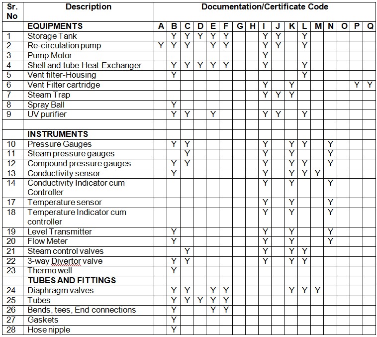
11. List of Documents Required for Distribution Loop:
| CODE | DOCUMENTS REQUIRED |
| A | Manufacturer’s Manuals – Preventive Maintenance (O.M.) |
| B | MOC Certificate |
| C | Leak Test Reports / Hydro Test Report |
| D | Surface Finish Report |
| E | Passivation Reports |
| F | Cleaning / Flushing Reports |
| G | Pump Performance Curves |
| H | Filter Test Reports |
| I | Engineering Specifications |
| J | Assembly Drawing |
| K | Manufacturer’s Catalogue |
| L | SEALS / Gasket-MOC |
| M | Test Certificate |
| N | Calibration Certification with traceability to National Standards |
| O | Basis of Design |
| P | Performance Certificate |
| Q | Validation Guide |
12 Design Qualification Approval:
FOR XYZ PVT. LTD. (DQ Preparation and review)
| NAME | SIGNATURE | DATE |
FOR XYZ PHARMACEUTICALS LIMITED
Reviewed By
| NAME | SIGNATURE | DATE |
Approved By
| NAME | SIGNATURE | DATE |
Don’t Miss This…
- Design Qualification of Purified Water Generation System as per USP Standards
- Design Qualification Of FBD in Pharmaceuticals
- Installation Qualification Protocol for Automatic four head Vial Sealing Machine
- Operational Qualification of Automatic High-Speed Linear Vial Washing Machine (Protocol)
- IQ of High-Speed Linear Vial Washing Machine
- Operational Qualification of Automatic Injectable Powder Filling With Rubber Stopping Machine

Naresh Bhakar is the Founder and Author at Pharmaguddu.com, bringing his extensive expertise in the field of pharmaceuticals to readers worldwide. He has experience in Pharma manufacturing and has worked with top Pharmaceuticals. He has rich knowledge and provides valuable insights and data through his articles and content on Pharmaguddu.com. For further inquiries or collaborations, please don’t hesitate to reach out via email at [email protected].