The purpose of the Blender Installation Qualification protocol is to establish documentary evidence to ensure that the Pillar Type Blender system received matches the Design specification and also to ensure that it is properly and safely installed. The equipment shall be used for blending different granules/powders to be used in the formulation. The equipment shall operate under dust dust-free environment and conditions as per the GMP requirements.
SERIAL NO.
ITEM DESCRIPTION
1.0
PROTOCOL APPROVAL
2.0
OVERVIEW:
2.1
Objective
2.2
Purpose
2.3
Scope
2.4
Responsibility
2.5
Execution Team
3.0
ACCEPTANCE CRITERIA
4.0
REVALIDATION
5.0
INSTALLATION QUALIFICATION PROCEDURE
5.1
System Description
5.2
Instruction for Filling the Checklist
5.3
Installation Check-List
5.4
Identification Of Major Components
5.5
Identification of Supporting Utilities.
5.6
Identification Of Safety Feature(s)
5.7
Identification Of Standard Operating Procedure
5.8
Verification of Drawings and Documents
5.9
Abbreviations
5.10
Deficiency And Corrective Action(s) Report(s)
5.11
Annexure (s)
6.0
INSTALLATION QUALIFICATION FINAL REPORT
6.1
Summary
6.2
Conclusion
6.3
Final report approval
1.0
PROTOCOL APPROVAL:
The signing of this approval page of the Protocol indicates agreement with the qualification approach described in this document. If a modification to the qualification approach becomes necessary, an addendum shall be prepared and approved.The protocol cannot be used for execution unless approved by the following authorities.
This Installation Qualification protocol of Pillar Type Blender. Has been reviewed and approved by the following persons:
FUNCTION
NAME
DEPARTMENT
SIGNATURE
DATE
PREPARED BY
QUALITY ASSURANCE
REVIEWED BY
PROJECTS / ENGINEERING
REVIEWED BY
PRODUCTION
APPROVED BY
QUALITY ASSURANCE
2.0
OVERVIEW:
2.1
OBJECTIVE:
The objective of developing and executing this protocol is to collect sufficient data about the Pillar Type Blender and define the qualification requirements and acceptance criteria for the Pillar Type Blender. Successful completion of these qualification requirements will ensure that the Pillar Type Blender was installed as required in the service area.
2.2
PURPOSE:
The purpose of this protocol is to establish documentary evidence to ensure that the Pillar Type Blender system received matches the Design specification and also to ensure that it is properly and safely installed. The equipment shall be used for blending different granules/powders to be used in the formulation. The equipment shall operate under dust dust-free environment and conditions as per the GMP requirements.
2.3
SCOPE:
This Protocol applies to the installation of a Pillar Type Blender at the tablet manufacturing facility in XYZ Pharmaceuticals & the subsequent documentation.
2.4
RESPONSIBILITY:
The following shall be responsible; Quality Assurance Officer/ Executive – For preparation of protocol projects / Engineering Head – For execution Production Head – For execution support Quality Assurance Head – For adequacy and final approval
2.5
EXECUTION TEAM:
The satisfactory installation of the Pillar Type Blender shall be verified by executing the qualification studies described in this protocol. The successfully executed protocol documents that the Pillar Type Blender is installed and is satisfactorily integrated. The execution team is responsible for the execution of the installation of the Pillar Type Blender. The execution team comprises of:
DEPARTMENT
DESIGNATION
NAME
SIGNATURE
DATE
PROJECTS
PRODUCTION
QUALITY ASSURANCE
3.0
ACCETANCE CRITERIA:
3.1
The Pillar Type Blender shall meet the system description given in the design qualification.
3.2
The Pillar Type Blender shall meet the acceptance criteria mentioned under the topic “Identification of major components”
3.3
The Pillar Type Blender system shall be operated by manual /PLC.
4.0
REVALIDATION CRITERIA:
The Pillar Type Blender has to be revalidated if
Any major changes in system components affect the performance of the system· After a major breakdown maintenance is carried out. As per the revalidation date and schedule
5.0
INSTALLATION QUALIFICATION PROCEDURE :
5.1
SYSTEM DESCRIPTION
Process Equipment Description:
The purpose of a container Blender is to mix various substances in dry powder and / Or granular form. Mixing can be achieved by selecting a suitable RPM and a suitable period depending on the product characteristic. The following setting can be done in the VFD:
i. RPM setting ii. Soft start iii. Soft stop
Complete equipment can be divided into the following sub-sections:
Drive shaft with bearing housing
Speed reduction system consisting of Brake Motor & Worm & Worm Wheel reduction gearbox Gear – Pinion arrangement.
Container holding arm.
Hydraulic power pack & cylinder.
Main electric panel (housing PLC, VFD) & safety railing with operating panel (having MMI, Push buttons).
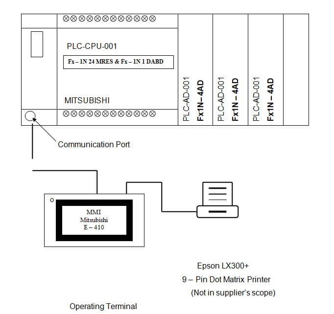
PLC Description
The main function of a PLC is to translate the instruction into the digital or analog codes needed to operate the device or equipment.
In the PLC system, its primary role is to gather data from the field instruments and show this information on the operator station. The instruments are linked to the system’s equipment and piping. The collected data is then used by the PLC to control the processes.
The user interface, based on an MMI E-410 (Mitsubishi), will assist the operator to supervise and control the process. According to the information shown, the operator can use the user interface to give commands to the PLC.
The PLC then executes the operator’s instructions. A Mitsubishi Family Fx 1N 24 MRES + Fx 1N 1DABD. PLC has been chosen as the Central Processing Unit (CPU).
The maximum Load-carrying capacity Hyd. System: 1200 Ltrs.
The maximum height of the Bin Holding arm from the ground: 1265 mm.
The minimum height of the bin holding arm from the ground: 1015 mm.
The PLC system layout for the FBE machine automation is as shown below:
5.2
INSTRUCTION FOR FILLING THE CHECKLIST
5.2.1
In case of compliance of the test use the word ‘Complies’ otherwise use ‘Does not comply‘ to indicate non-compliance.
5.2.2
For identification of the components of the equipment and utilities use the word ‘’yes’’ to show its presence and use ‘No’ to indicate the absence of the identity
5.2.3
Give detailed information in the summary and conclusion part of the Installation Qualification report.
5.2.4
Whichever column is blank or not used ‘NA’ shall be used.
5.3
INSTALLATION CHECKLIST:
The installation checklist is as follows:
Sr. NO.
STATEMENT
YES / NO
CHECKED BY(SIGN)
DATE
01.
Verify that the “As Built” drawing is complete and represents the design concept.
02.
Verify that major components are securely anchored and shockproof.
03.
Verify that there is no observable physical damage.
04.
Verify that there is sufficient room provided for servicing.
05.
All access ports are examined and cleared of any debris.
06.
Walking access to roof-mounted equipment provided.
07.
Equipment identification name plate visible.
08.
Verify that all piping and electrical connections are done according to the drawings.
09.
Safe electrical connections.
10.
A wiring diagram affixed to the inside section of the control panel.
11
Units installed on the foundation are secure in place as per the manufacturer’s recommendations.
5.4
IDENTIFICATION OF MAJOR COMPONENTS :
Describe each critical component and check them and fill out the inspection checklist.
Brake motor, TEFC, Non – Flameproof Squirrel cage, 3-phase induction
Model
Flange mounted
Capacity
3 HP x 1440 RPM.
9. Bearings.
Tapper Roller Bearing
32024 – 1no. / 32026 – 1no.
Ball Bearing
6208 – 8nos.
10. Variable Frequency Drive
Type
E series 440 V class AC drive
Model
FR E 540 – 5.5K.
CapacityM.O.C
5.5K.
M.S
11. Gear– Pinion Reduction Drive.
Type
Helical.
Gear
151
Pinion
20
Reduction Ratio
7.55:1
Module
4.5
12. Hydraulic Power Pack std. components.
Gear Pump(make – Rexroth)
1 PF2 G24X/004 RA01 MR.
Pressure Relief Valve(Make – Rexroth)
DBOH 6P 17/200.
Check valve(Make – shakti)
¼“BSP
Flow Control Valve(Make – Rexroth)
Z2FS 624X/2QV
5.5
IDENTIFICATION OF SUPPORTING UTILITIES:
UTILITY
PROPERLY IDENTIFIED & CONNECTED (YES/NO)
CHECKED BY (SIGN)
DATE
1) Electricity:3 Phase, 440V, 50 HzKw / HP: 3 HP x 2Nos. Main drive motor2 HP x 1No. Power Pack motor.
5.6
IDENTIFICATION OF SAFETY FEATURES:
Identify and record the safety features (if any) and their function in the following tables :
Safety Features Description
Function
Identified By(Sign)
Date
1. Container / Bin does not rotate.
Until the drive assembly with the Bin is lifted to the set height.
2. Blender does not start.
Until the safety railing is closed.
5.7
IDENTIFICATION OF STANDARD OPERATING PROCEDURE (SOP)
The following Standard Operating Procedures were identified as important for the effective performance of Pillar Type Blender.
1
Operation of Pillar type blender.
2
Cleaning of Pillar-type blender.
3
Preventive maintenance of Pillar type blender.
5.8
VERIFICATION OF DRAWING AND DOCUMENTS:
The following documents are reviewed and attached as listed below:
Sr. No.
DRAWING AND DOCUMENT DETAIL
CHECKED BY (SIGN)
DATE
5.9
ABBREVIATIONS
The following Abbreviations are used in the installation qualification protocol of the Air handling unit
cGMP: current Good Manufacturing PracticesGEP: Good Engineering practicesMS: Mild steelNFLP: Non-Flame ProofSS: Stainless SteelKW: Kilo WattDQ: Design QualificationFAT: Factory acceptance test BLD: Blender
5.10
DEFICIENCY AND CORRECTIVE ACTION(S) REPORT(S)
The following deficiency was identified and corrective actions were taken in consultation with the validation team.
Description of deficiency:
Corrective action(s) taken:
Reviewed By:
Date:
5.11 Annexure(s):
Sr.No.
Annexure No.
Title of Annexure
6.0
INSTALLATION QUALIFICATION FINAL REPORT:
All the IQ data sheets and discrepancy reports shall be reviewed by the validation team to prepare a summary report. The summary of IQ shall be used to draw conclusion for approval of the Blender installation qualification protocol report.
6.1
SUMMARY
6.2
CONCLUSION
6.3 FINAL REPORT APPROVAL
It has been verified that all tests required by the Blender Installation Qualification protocol are completed, reconciled, and attached to this protocol or included in the qualification summary report. Verified that all amendments and discrepancies are documented, approved, and attached to this protocol.
The signature in the space below shows that It has carefully examined every detail in this report about the Pillar Type Blender and confirmed that everything is satisfactory. Any differences or issues have been sorted out.
Naresh Bhakar is the Founder and Author at Pharmaguddu.com, bringing his extensive expertise in the field of pharmaceuticals to readers worldwide. He has exprience in Pharma manufactring and worked with top Pharmaceuticals. He has rich knowledge and provides valuable insights and data through his articles and content on Pharmaguddu.com. For further inquiries or collaborations, please don't hesitate to reach out via email at [email protected].