
The purpose of the Installation Qualification Protocol for Automatic Capsule Filling Machine is to establish documentary evidence to ensure that the Automatic capsule filling machine system received matches the Design specification and also to ensure that it is properly and safely installed.

| SERIAL NO. | ITEM DESCRIPTION | |
| 1.0 | PROTOCOL APPROVAL | |
| 2.0 | OVERVIEW: | |
| 2.1 | Objective | |
| 2.2 | Purpose | |
| 2.3 | Scope | |
| 2.4 | Responsibility | |
| 2.5 | Execution Team | |
| 3.0 | ACCEPTANCE CRITERIA | |
| 4.0 | REVALIDATION | |
| 5.0 | INSTALLATION QUALIFICATION PROCEDURE | |
| 5.1 | System Description | |
| 5.2 | Instruction for Filling the Checklist | |
| 5.3 | Installation Check-List | |
| 5.4 | Identification Of Major Components | |
| 5.5 | Identification of Supporting Utilities. | |
| 5.6 | Identification Of Safety Feature(s) | |
| 5.7 | Identification Of Standard Operating Procedure | |
| 5.8 | Test instrument details | |
| 5.9 | Identification Of Component to be Calibrated | |
| 5.10 | Verification of Drawings and Documents | |
| 5.11 | Abbreviations | |
| 5.12 | Deficiency And Corrective Action(s) Report(s) | |
| 5.13 | Annexure(s) | |
| 6.0 | INSTALLATION QUALIFICATION FINAL REPORT | |
| 6.1 | Summary | |
| 6.2 | Conclusion | |
| 6.3 | Final report approval | |
| 1.0 | PROTOCOL APPROVAL: |
The signing of this approval page of the IQ Protocol for Automatic Capsule Filling Machine indicates agreement with the qualification approach described in this document. If a modification to the qualification approach becomes necessary, an addendum shall be prepared and approved. The protocol cannot be used for execution unless approved by the following authorities.
This Installation Qualification protocol for the Automatic capsule filling machine has been reviewed and approved by the following persons:
| FUNCTION | NAME | DEPARTMENT | SIGNATURE | DATE |
| PREPARED BY | QUALITY ASSURANCE | |||
| REVIEWED BY | PROJECTS / ENGINEERING | |||
| REVIEWED BY | PRODUCTION | |||
| APPROVED BY | QUALITY ASSURANCE |
| 2.0 | OVERVIEW: |
| 2.1 | OBJECTIVE: |
| The objective of developing and executing this protocol is to collect sufficient data about the ‘Automatic capsule filling machine’ and define the qualification requirements and acceptance criteria for the Automatic capsule filling machine. Successful completion of these qualification requirements will ensure that the Automatic capsule-filling machine is installed as required in the production area. The objective of the installation qualification is to prove that each activity proceeds as per design specification and the tolerances prescribed there in the document and is the same at utmost transparency. | |
| 2.2 | PURPOSE: |
| The purpose of this protocol is to establish documentary evidence to ensure that the Automatic capsule filling machine system received matches the Design specification and also to ensure that it is properly and safely installed. The purpose of Automatic capsule filling machine shall be used for capsule filling different capsule sizes to be used in the formulation. The equipment shall operate under a dust-free environment and conditions as per the GMP requirements. | |
| 2.3 | SCOPE: |
| This Protocol applies to the installation of an Automatic capsule-filling machine at the tablet manufacturing facility in Pharmaceuticals & the subsequent documentation. |
| 2.4 | RESPONSIBILITY: |
| The following shall be responsible; Quality Assurance officer/ Executive – For the preparation of protocol. Projects / Engineering Head – For execution. Production Head – For execution support. Quality Assurance Head – For adequacy and final approval |
| 2.5 | EXECUTION TEAM: |
| The satisfactory installation of the Automatic capsule-filling machine shall be verified by executing the qualification studies described in this protocol. The successfully executed protocol documents that the Automatic capsule filling machine was installed and is satisfactorily integrated. The execution team is responsible for the execution of the installation of the Automatic capsule filling machine. The execution team comprises of: |
| DEPARTMENT | DESIGNATION | NAME | SIGNATURE | DATE |
| PROJECTS/ENGINEERING | ||||
| PRODUCTION | ||||
| QUALITY ASSURANCE |
| 3.0 | ACCETANCE CRITERIA: |
| 3.1 | The Automatic Capsule Filling Machine shall meet the system description given in the design qualification. |
| 3.2 | The Automatic Capsule Filling Machine shall meet the acceptance criteria mentioned under the topic “Identification of major components”. |
| 3.3 | The Automatic Capsule Filling Machine system shall be operated by manual /PLC. |
Related: Installation Qualification Protocol for Blister Packing Machine with Annexures
| 4.0 | REVALIDATION CRITERIA: |
| The Automatic Capsule Filling Machine has to be revalidated if: | |
| Any major changes in system components affect the performance of the system. After major breakdown maintenance is carried out. As per the revalidation date and schedule. |
| 5.0 | INSTALLATION QUALIFICATION PROCEDURE: | |
| 5.1 | AUTOMATIC CAPSULE FILLING MACHINE SYSTEM DESCRIPTION | |
PROCESS EQUIPMENT DESCRIPTION
The basic (Equipments) consists of the following subassemblies:
1. Structure Assembly:
This houses the main drive motor, powder drive motor, pneumatic and vacuum piping, all drive elements, and electrical control cabinet. The structure is enclosed on all four sides by removable covers. Removing the hand-wheel side cover exposes the filter regulator lubricator unit of the compressed air system, the pressure switch, and the main drive motor clutch. Removing the cover below the exit chute exposes the cam switch box and drive mechanism. When the cover located below the empty capsule loading area is removed, an electrical control panel is exposed.
2. Drive assembly:
This consists of the main motor, drive shaft, gears, cams, cam followers, bearings, housings, and brackets. Rotary indexing motion is given to the turret, dosing disc, and a reciprocating motion is given to various sections that move vertically by specially designed cams.
3. Turret Assembly:
The turret is a cylindrical disc. It has 8 pairs of cap and body bush holder plates with the cap plate located above the body plate. Each pair is radially equidistant around the turret center. The turret also houses a pneumatic cylinder and cams for providing motion to the cap and body bush holder plates.
4. Empty Capsule Holder Assembly:
This consists of a capsule hopper, capsule reservoir, magazine, rectifier block, horizontal finger assembly, and vacuum block. The reservoir has a baffle plate to regulate the flow of capsules in the reservoir. The magazine is mounted on a shaft. The vertical finger assembly and the capsule-releasing fingers are fitted on the magazine. A handle is provided to start or stop the release of capsules to the rectifier block. The released capsules are pushed by the horizontal finger assembly. A vacuum block located below the body bush holder plate moves up and down.
5. Powder Filling Device:
This consists of a hopper, stirrer, feed tube, powder level sensing device, and powder tub. The powder hopper is a stainless steel container fitted with an acrylic window. A powder stirrer is mounted centrally in the hopper and driven by a separate motor. At the delivery end of the hopper, an adjustable gate is provided to control the rate of powder flow and to facilitate the removal of powder at the end of the shift. The powder level in the powder tub is sensed by a capacitive-type proximity switch.
6. Tamping Station:
The product to be filled is fed from the hopper to the dosing disc. Due to the centrifugal force of the dosing chamber drive the product is carried to the outer edges of the dosing disc to the tamping plungers. The product is then compressed five times before being transferred into the capsule.
7. Pin Plate Assembly:
This consists of a plate on which various segments of pin for different applications are fitted. At No. 5 unopened capsules are collected in a box which are ejected out by pins. Similarly at stations 6,7& there are pins for the closing of capsules ejecting the capsule from the exit chute and cleaning of the capsule.
8. Electrical control assembly:
This electrical control panel is mounted inside the structure of the machine. The mains ON / OFF switch is on the cover of the machine. The drive ON / OFF, control ON, speed regulator, and the emergency OFF. Switches are mounted on the pendent of the machine. Inching facility is provided for easy checking of the various settings on the machine. The display screen of the PLC has various selector keys for performing various operations. The control cabinet inside the structure houses the AC drive, The PLC, MCB`s contractors, and overload relays.
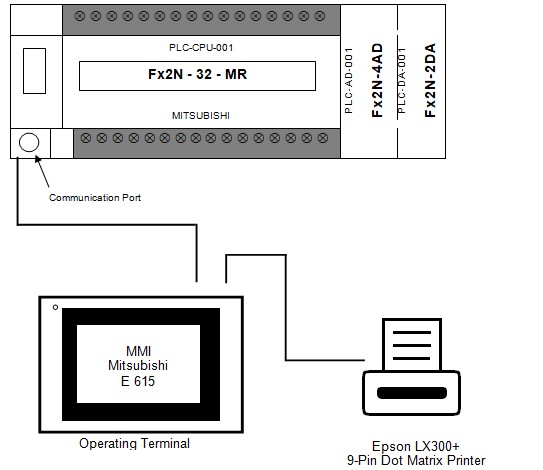
PLC Description:
The main function of a PLC is to translate the instructions into the digital codes needed to operate the device or machine & to collect data from field instrumentation & display the information on the operator station. The instruments are connected to the system equipment. The collected data will be utilized by the PLC process control. The user interface, based on an industrial-type MMI. Will assist the operator in supervising and controlling the process. Based on the displayed information the operator, utilizing the user interface, can provide commands to the PLC. The PLC then executes the operator’s instructions. A Mitsubishi family FX 2 N 32 MT ESS PLC has been the central processing unit (CPU).
The PLC system layout for the automatic capsules filling machine automation is as shown below:
| 5.2 | INSTRUCTION FOR FILLING THE CHECKLIST |
| 5.2.1 | In case of compliance of the test use the word ‘Complies’ otherwise use ‘Does not comply‘ to indicate non-compliance. |
| 5.2.2 | To identify the components of the equipment and utilities, use the word ‘yes’ to indicate their presence and use ‘no’ to indicate their absence. |
| 5.2.3 | Give detailed information in the summary and conclusion part of the Installation Qualification report. |
| 5.2.4 | Whichever column is blank or not used ‘NA’ shall be used. |
Related: Auto Coater Installation Qualification Protocol/ Annexures
| 5.3 | INSTALLATION CHECKLIST: |
| The installation checklist is as follows: |
| Sr. NO. | STATEMENT | YES / NO | CHECKED BY(SIGN) | DATE |
| Verify that the “As Built” drawing is complete and represents the design concept. | ||||
| Verify that major components are securely anchored and shockproof. | ||||
| Verify that there is no observable physical damage. | ||||
| Verify that there is sufficient room provided for servicing. | ||||
| Ensure that all piping and electrical connections adhere to the drawings. | ||||
| All-access ports are examined and cleared of any debris. | ||||
| Safe electrical connections. | ||||
| A wiring diagram affixed to the inside section of the control panel. | ||||
| Equipment identification nameplate visible. | ||||
| Units installed on the foundation are secure in place as per manufacturer’s recommendations. |
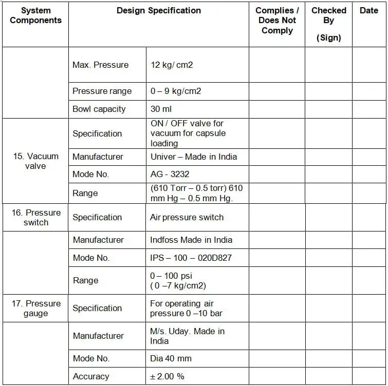
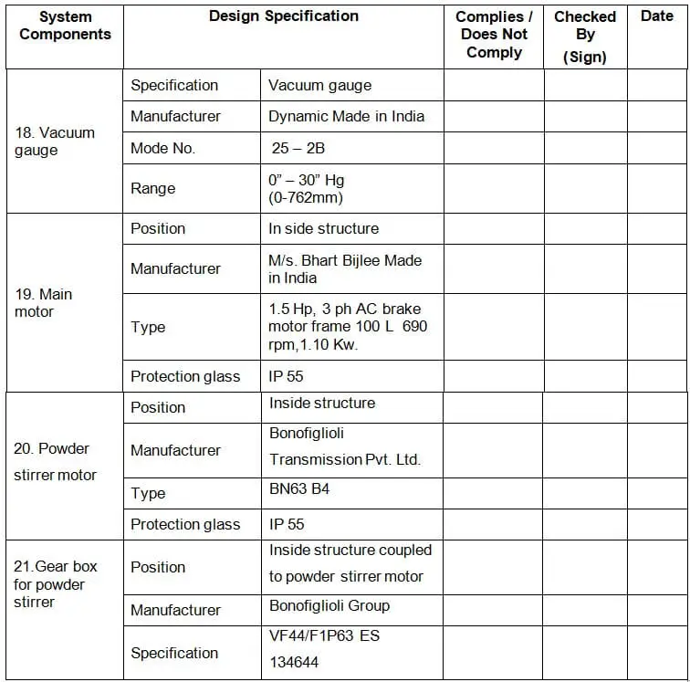
| 5.4 | IDENTIFICATION OF MAJOR COMPONENTS: | |||||
| Describe each critical component and check them and fill out the inspection checklist. | ||||||
| System Components | Design Specification | Checked By(Sign) | Date | |||
| 1. Equipment Description | Name | — | ||||
| Material | Mild steel, painted, enclosed on all sides of SS 304 covers. | |||||
| Capacity | 25000/Hrs. | |||||
| Model | AF 25 T | |||||
| Serial No. | — | |||||
| 2. Drive Assembly | Position | — | ||||
| Manufacturer | PAM India | |||||
| Material | Alloy steel | |||||
| Timer belt | HTD 8 mm pitch | |||||
| Bearings | SKF / INA / IKO / RNST | |||||
| System Components | Design Specification | Complies / Does Not Comply | Checked By(Sign) | Date | ||
| 3. Turret Assembly | Position | Cylindrical disc above machine top, holding cap & body bush holder | ||||
| Manufacturer | PAM India | |||||
| Material | Aluminium casting | |||||
| Surface finish | Electroless nickel plated | |||||
| 4. Loader assembly | Position | Above machine top plate to load empty capsule in bushes | ||||
| Manufacturer | PAM India | |||||
| Material | Aluminium | |||||
| Surface finish | Black hard anodized | |||||
| Rectifier raceway & finger assembly | Half-hard brass electro-nickel plate | |||||
| Reservoir & baffled plate | SS 316, mirror-polished | |||||
| System Components | Design Specification | Complies / Does Not Comply | Checked By(Sign) | Date | |
| 5. Powder filling device | Position | Above machine top plate to provide powder for filling operation | |||
| Manufacturer | PAM India | ||||
| Material | Stainless Steel316L | ||||
| Hopper | SS 316, Mirror polish | ||||
| 6. Pin plate assembly | Position | Above machine top plate to perform various operations lick closing, ejection, bush cleaning removing unopened capsules. | |||
| Manufacturer | PAM India | ||||
| Material | Alloy steel | ||||
| Surface finish | Electro less nickel plated | ||||
| Open, closing, Ejection pin | SS 316 | ||||
| Bush cleaning pin | Brass | ||||
| System Components | Design Specification | Complies / Does Not Comply | Checked By(Sign) | Date | |
| 7. Limit switch | Quantity | 4 Nos. | |||
| Specification | Door safety switch 1 NO + 1NC | ||||
| Manufacturer | Essendeinki – Made in India | ||||
| Model No. | MBC 1 | ||||
| Actuating force | 723 gms. (Max.) | ||||
| Release force | 170 gms. (Min.) | ||||
| Pre Travel | 1.5 mm (Max.) | ||||
| Over travel | 4.6 mm | ||||
| Movement differential | 0.08 mm | ||||
| Salient features | Spring plunger actuator protected by a synthetic rubber cowl. | ||||
| 8. Proximity switches (Capacity) for Capsule hopper | Specification | Capsule low-level switches | |||
| Quantity | 1 No. | ||||
| Manufacturer | IFM made in Germany | ||||
| Model No. | KG5043 3008 BPK/IN | ||||
| Sensing range | 8 mm |
| Components | Design Specification | Complies / Does Not Comply | Checked By(Sign) | Date | |||
| 9. Proximity switches (Capacity) for powder level | Specification | Powder level switches | |||||
| Quantity | 1 No. | ||||||
| Manufacturer | IFM made in Germany | ||||||
| Model No. | KG5043 3008 BPK/IN | ||||||
| Sensing range | 8 mm | ||||||
| 10. Proximity switches (inductive) | Specification | To provide signals for various operation | |||||
| Position | Cam switch box | ||||||
| Quantity | 2 No. | ||||||
| Manufacturer | TAP made in India | ||||||
| Model No. | GLP – 12APS | ||||||
| Sensing range | 1 mm | ||||||
| 11. Proximity switches (inductive) for hand wheel | Specification | To provide signals for various operation | |||||
| Position | Inside structure & near wheel shaft | ||||||
| Quantity | 1 No. | ||||||
| Manufacturer | TAP made in India | ||||||
| Model No. | GLP – 12APS | ||||||
| Sensing range | 1 mm | ||||||
| System Components | Design Specification | Complies / Does Not Comply | Checked By(Sign) | Date | |||
| 12. Proximity switches (inductive) for the main motor | Specification | To provide signals for various operation | |||||
| Position | Near the main motor clutch | ||||||
| Quantity | 1 No. | ||||||
| Manufacturer | TAP made in India | ||||||
| Model No. | GLP – 12APS | ||||||
| Sensing range | 1 mm | ||||||
| 13. Proximity switches (inductive) for PMM motor | Specification | To provide signals for various operation | |||||
| Position | On PMM motor gearbox | ||||||
| Quantity | 1 No. | ||||||
| Manufacturer | TAP made in India | ||||||
| Model No. | GLP – 12APS | ||||||
| Sensing range | 1 mm | ||||||
| 14. Filter regulator | Specification | To provide filtered air at a set pressure | |||||
| Manufacturer | Airmatic Made in India | ||||||
| Model No. | MB 10 – 023 | ||||||
| Size | 6 mm | ||||||
| System Components | Design Specification | Complies / Does Not Comply | Checked By(Sign) | Date | ||||
| 22. Door cylinder | Position | Polycarbonate door | ||||||
| Manufacturer | Munjal Showa | |||||||
| Specification | Stroke 175 | |||||||
| 23. Pneumatic cylinder | Position | Inside turret well, exit chute | ||||||
| Manufacturer | Rexroth Made in India | |||||||
| Specification | Compact cylinder 20 mm dia 4 mm stroke, DG 6-10, Part no. 3620, ADVU 20 x 10 | |||||||
| Operating range | 6 kg / cm2 | |||||||
| 24. Pneumatic cylinder for capsule loading | Position | Inside turret well, exit chute | ||||||
| Manufacturer | Rexroth Festo Made in India | |||||||
| Specification | Compact cylinder 20 mm dia 10 mm stroke, ADVU – 20 – 10 – A, Part No. 156515. | |||||||
| Operating range | 10 kg / cm2 | |||||||
| 25. Pneumatic cylinder for group sampling | Position | Below Exit chute | ||||||
| Manufacturer | Festo | |||||||
| Specification | DG – 6 –10, 2620, T008, Dia10, 6 mm stroke | |||||||
| Operating range | 6 kg /cm2 | |||||||
| 26. Solenoid valve | Position | On pneumatic panel inside the structure | ||||||
| Manufacturer | Festo made in India | |||||||
| Specification | Single solenoid MFH – 1- 1 / 8 | |||||||
| Operating range | 6 KG / CM2 | |||||||
| 27. Timer belt | Position | Drive assembly, Cam switch box | ||||||
| Manufacturer | Optibelt Made in Germany | |||||||
| Specification | 8 mm pitch, 1200 mm length, 30 mm width, 150 teeth. | |||||||
| 28. Chain | Position | Drive assembly, Cam switch box | ||||||
| Manufacturer | Diamond Simplex Made in India | |||||||
| Specification | ½” Pith x 5 /16” roller dia, 33 link | |||||||
| 29. PLC | CPU Make | Mitsubishi Made Japan | ||||||
| Position | Inside the control panel | |||||||
| Model No. | F x 2N – 32 – MT | |||||||
| PLC Input/output | 16 Input / 16 output | |||||||
| 30. A.C. drives | Position | Inside the control panel | ||||||
| Manufacturer | Mitsubishi | |||||||
| Specification | FR – S520SE | |||||||
| 31. MMI | Make | E 615 | ||||||
| Position | On the pendant control box | |||||||
| Manufacturer | Beijers | |||||||
| Keyboard | Touch screen | |||||||
| Serial interface | RS – 232, RS 422 | |||||||
| Display | 5.7” Diagonal | |||||||
| Supply voltage | + 24 VDC, ± 20 % | |||||||
| 32. Vacuum Gauge | Specification | For operating Air pressure 0 – 10 bar | ||||||
| Manufacturer | M / s SMC corporation | |||||||
| Model No. | I – I SE30 – 01- 65 | |||||||
| Accuracy | 0.1 – 1 KBP | |||||||
| 5.5 | IDENTIFICATION OF SUPPORTING UTILITIES: |
| UTILITY | PROPERLY IDENTIFIED & CONNECTED (YES/NO) | CHECKED BY (SIGN) | DATE |
| 1) Electricity: 3 Phase 440 Volts, 50Hz | |||
| 2) Compressed air: 6 kg/cm2 |
| 5.6 | IDENTIFICATION OF SAFETY FEATURES: | |||
| Identify and record the safety features (if any) and their function in the following tables: | ||||
| Safety Features Description | Function | Identified By(Sign) | Date | |
| . | ||||
| 5.7 | IDENTIFICATION OF STANDARD OPERATING PROCEDURE (SOP) | |
| The following Standard Operating Procedures were identified as important for the effective performance of the Automatic capsule-filling machine. | ||
| 1. | Operation of Automatic capsule filling machine. | |
| 2. | Cleaning of Automatic capsule filling machine. | |
| 3. | Preventive maintenance Automatic capsule filling machine. | |
| 5.8 | TEST INSTRUMENT DETAILS |
| Instrument/Equipment required: 1. RPM-meter 2. Ammeter |
| 5.9 | IDENTIFICATION OF COMPONENT TO BE CALIBRATED |
| In the High Shear Mixer Granulator, the following are the components, that need calibration. They shall be calibrated during/ before installation of the equipment at the site: Following are the components: 1. Pressure Measurement: | |
| 5.10 | VERIFICATION OF DRAWING AND DOCUMENTS: | ||
| The following documents are reviewed and attached as listed below: | |||
| Sr. No. | DRAWING AND DOCUMENT DETAIL | CHECKED BY (SIGN) | DATE |
| 1. | |||
| 2. | |||
| 3. | |||
| 4. | |||
| 5. | |||
| 6. | |||
| 7. | |||
| 8. | |||
| 9. | |||
| 10. | |||
| 11. | |||
| 5.11 | ABBREVIATIONS |
| The following Abbreviations are used in the installation qualification protocol of the Air handling unit | |
| CMF: Capsule filling machine MOC: Material of construction RPM: Rotation per minute BHP: Break horse power HMI/MMI: Human/Man-Machine Interface FAT: Factory acceptance test CFM: Cubic Feet Per Minute AISI: American Iron & Steel Institute GEP: Good Engineering Practices FLP: Flame Proof MS: Mild steel |
| 5.12 | DEFICIENCY AND CORRECTIVE ACTION (S) REPORT (S) |
| The following deficiency was identified and corrective actions were taken in consultation with the validation team. | |
| Description of deficiency: |
| Corrective action(s) taken: |
Reviewed By:
Date
5.13 Annexure(s):
| Sr.No. | Annexure No. | Title of Annexure |
| 6.0 | INSTALLATION QUALIFICATION FINAL REPORT: |
| All the IQ data sheets and discrepancy reports shall be reviewed by the validation team to prepare a summary report. The summary of IQ shall be used to conclude approval of the installation qualification report. |
| 6.1 | SUMMARY |
| 6.2 | CONCLUSION |
6.3 FINAL REPORT APPROVAL
Includes your Final Report Approval here.
| NAME | DESIGNATION | DEPARTMENT | SIGNATURE | DATE |
| PROJECTS / ENGINEERING | ||||
| PRODUCTION | ||||
| QUALITY ASSURANCE |
-
by
-