Quality Control Specialist | Industry Experience
✓ Reviewed by: Pankaj Sharma - Quality Control Specialist
Reviewed for Quality Control accuracy, laboratory practices, analytical methods, and technical relevance
📅 Last Updated: March 23, 2023
1.0 Objective: 1.1 To lay down the procedure for the Operation and Calibration of Dissolution Apparatus (Tester).
2.0 Scope: 2.1 This SOP shall be applicable to the Analytical development at Pharmaceutical Analytical Lab.
3.0 References: 3.1 In-House SOP of dissolution apparatus
4.0 Responsibility:
4.1 AD Executive/Sr. Executive.
4.2 To follow the procedure for calibration as per SOP.
3.3 To maintain the log book/Format, calibration record, and history card.
5.0 Accountability:
5.1 Manager AD
6.0 Procedure for Dissolution Apparatus:
6.1 Preliminary Checks:
6.1.1 Ensure that the system is clean and free from dust. In case cleaning is required, clean with tissue paper.
6.1.2 Ensure that the instrument is connected to the uninterrupted power supply.
6.1.3 Check the purified water in the bath. It should be clear and up to the mark.
6.2 Precautions :
6.2.1 Replace the water in the water bath once a week or whenever it is found to be turbid and clean the water bath before adding the fresh water.
6.2.2 Disconnect the power supply while cleaning the water bath.
6.2.3 Do not pull or force the paddle or basket.
6.2.4 Do not push the shafts forcefully.
6.2.5 Check the integrity of basket mesh visually prior to use.
6.2.6 Baskets and paddles must be verified for any damage prior to use. Deformed baskets or denied paddles must be taken out of use and discarded.
6.2.7 Check the jars while lowering the paddle or basket assembly.
6.2.8 After completion of the work removes and clean the jars, paddles/baskets. Keep the paddles/baskets in a drawer. Keep the cleaned jars in their original place.
6.2.9 Always keep the shaft assembly in the lowest position at the end of the day and when the instrument is not in use.
6.2.10 Fit paddles or baskets to respective instruments and in respective positions only.
6.2.11 Switch “OFF” the instrument when not in use.
6.3 Operating Instructions for Dissolution Apparatus (Tester):
6.3.1 Switch “ON” the power from the main switch, and a red LED will glow. The display will show “ELECTROLAB DISSOLUTION TESTER EDT-14LX”.
6.3.2 This screen will flash once and then the instrument will show the idle screen which displays Tank warming, Bath temperature, and HTR ON. Actual RPM, Bath temperature, the temperature being measured by External Probe, and the Current time will be displayed. The setting of these parameters can be done as follows.
6.3.3 Switch “ON” the heater from heater switch. A green LED will glow on the display screen Tank warming will display along with current bath temperature and HTR ON. The instrument will get ready for the test till it gets the desired temperature range and a beep sound will come and display screen will show HTR OFF. Now the instrument is ready and desired parameters according to the monograph can be entered.
6.3.4 Press the Platform motor switch “ON” from the front panel to make the lift unit down. The lift will stop automatically at maintaining the 25 mm + 2 mm distance between the inside bottom of the test vessel and the Basket/Paddle Blade.
6.3.5 For Setting RPM
Press the RPM key from the front panel. Press numeric key to register the RPM range from 20 to 300. Press F1 key to turn on motor & F2 key to turn it off. If RPM is out of range error screen will be displayed.
6.3.6 For Setting temperature
Press the TEMP key from the front panel. Press numeric key to register the temperature range from 20 to 40ºC/20 to 55ºC. Press F1 or F3 to Turn On/Off heater. If temp. is out of range error screen will be displayed.
6.3.7 For Setting Protocol
Press 2 to enter protocol menu. Press 1 to enter LOAD protocol, 20 programmable protocols can be downloaded.
Protocol no. can be loaded using UP/DOWN key & to register the No. Enter key needs to be pressed.
Press F1 to load next protocol, Press F2 to load previous protocol, and F3 to go back to previous screen.
6.4 Operating Instructions for Dissolution Apparatus:
6.4.1 Check the water level of the bath from the mark given at the side of the bath of apparatus and fill up to the mark if necessary.
6.4.2 Check the pH of the medium at 37 ± 0.5°C. Adjust the pH to ± 0.05 units of the pH specified in the monograph, in the case of buffered solutions.
6.4.3 Fill the stated volume of dissolution medium in the cleaned bowls of the apparatus.
6.4.4 Switch ON the power. The instrument will initialize itself. The display will show “ELECTROLAB EDT-14LX Dissolution Apparatus Tester”.
6.4.5 This screen will flash once and then the instrument will show the idle screen which displays Protocol No., Actual RPM, Bath Temperature, the Temperature being measured by External Probe, and the Current time will be displayed. The setting of these parameters can be done as follows.
Related: Types of Dissolution Test Apparatus
6.4.6 The protocol can be changed using Increment, and Decrement. Press the ENTER key to register the value.
6.4.7 For setting RPM press the RPM key from the front panel. The setting screen for the RPM will be displayed. RPM can be set from 20 to 300 using the UP/DOWN/DIGIT SCROLL key.
6.4.8 After setting the desired speed for the stirrer, select the stirrer status “start” or “stop” by using F1 or F2 keys respectively. The current status for the active key is indicated by the < > symbol for F1 or F2 key. The speed of the stirrer can be changed even when the stirrer is ON. Press the ENTER key from the front panel to register the value. After pressing the ENTER key, the instrument will display the idle screen with the actual RPM value.
6.4.9 For the Temperature setting press the TEMP key from the front panel, this will display the screen for the temperature setting. Temperature setting can be done by using the UP/DOWN/DIGIT SCROLL keys.
6.4.10 After the temperature setting switch ON the heater using the function key F1 or can switch OFF the heater using function key F2. The current status for the active key is indicated by the < > symbol for F1 or F2 key. Press the ENTER key from the front panel to register the value. After pressing the ENTER key, the instrument will display the idle screen with the actual Temperature value.
6.4.11 If the Temperature controller has started then the TEMP. ON LED on the front panel will glow. The Pump and the Heater ON LED on the Temperature controller unit will glow.
6.4.12 For the sample interval setting press the TIME key from the front panel. This will display the screen for setting the Sample No. and the Sample Interval Time. A maximum 16 sample interval can be set and the sample time can be set from 00 minutes to 23 hours: 59 minutes. The desired value for the sample no, and the sample time can be set by using the UP/DOWN key. Switch between sample No. or sample interval can be done by using the DIGIT SCROLL key. Press the ENTER key to register the value.
6.4.13 Clock setting can be done by using the UP/DOWN/DIGIT SCROLL keys. This is the default setting and it will always show the current time.
6.4.14 Date setting can be done by using the UP/DOWN/DIGIT SCROLL keys. This is the default setting and it will always show the current Date.
6.5 Dissolution Apparatus Operation:
6.5.1 Select the driving shaft as per monograph basket type (Apparatus 1) or paddle type (Apparatus 2). Insert the shaft as follows :
6.5.2 Lift the stirrer unit up to its topmost position and align the shaft to be inserted with the corresponding spindle shaft.
6.5.3 Press the paddle lock button with your thumb while supporting the back of the shaft with your fingers.
6.5.4 Gently insert the paddle into spindle hole. Push in the paddle shaft till the bottom edge of flat span on paddle reaches close to the lower face of spindle shaft. The end position is recognized by a click when the button snaps into groove of the paddle.
6.5.5 Release the lock button. The paddle then gets locked with the spindle at required height with respect to stirrer unit.
6.5.6 Press the DOWN arrow key from the front panel to make the lift unit down. The lift will stop automatically at maintaining the 25 mm + 2 mm distance between the inside bottom of the test vessel and the Basket/Paddle Blade.
6.5.7 Weigh the tablets /capsules/pellets under test and designate them with reference to the bowl number.
6.5.8 Place the Test Sample in the Test Vessel. Start the stirrer. Press the START key from the front panel to start the test. The instrument will now show the Run Time Screen.
6.5.9 The Run Time Screen will display the Protocol Running, Step No., The Elapsed Sampling Time for that particular step, the Actual RPM of the stirrer, Actual Bath Temperature, and the Temperature are measured by the External Probe. The RUN LED on the front panel will glow indicating the instrument is in RUN condition.
6.5.10 Withdraw sample at the end of the time specified or at the time intervals within a tolerance of ±2% of the time limit from a zone midway between the surface of the dissolution medium and at the top of the rotating shaft basket or blade, not less than 1.0 cm away from the wall of the bowl.
6.5.11 Replace the same volume of dissolution medium kept under same condition into the bowls (in case of slow-release tablets) after each sampling.
6.5.12 After completion of dissolution lift the stirrer assembly using the Up/down keys.
6.5.13 Clean the jars and spindles.
6.5.14 Dilute and filter the sample as per the monograph/MOA.
6.5.15 Analyze the sample as per the monograph.
6.5.16 Calculate the percentage of the drug release.
6.5.17 Check the compliance of the dosage units for dissolution as per the monograph.
6.5.18 If the temperature probe is not connected, then the screen will display “PrbOp”. If the External Probe is connected and not kept in the test vessel/bath, then the instrument will display the room temperature.
6.5.19 If the Heater is started and the desired temperature is reached and the lift is properly at the down position then the READY LED on the front panel will glow. At this time the instrument is displaying the idle screen.
6.5.20 If the instrument is not properly lowered and if the Start key is pressed from the front panel then the instrument will prompt an error screen as the lift is not at a lower position and hence the test cannot start.
6.5.21 If the temperature is not reached the Set value and the Start key is pressed from the front panel then the instrument will prompt an error screen stating the temperature has not yet been reached and hence the test cannot start.
6.5.22 To RESET the instrument while in RUN condition, press the RESET switch provided on the rear right-hand side. The test will be aborted and the instrument will display the idle screen.
6.5.23 To halt the test, press the STOP key once. The test will be halted and the halt time will be displayed. The HALT LED on the front panel will start blinking. The user can either start the test again or can stop the test by pressing F1 or F2 keys respectively.
6.5.24 If the F1 key is pressed then the test will start from the point it had stopped and the Halt Time is not counted. The instrument will display the RUN screen again.
6.5.25 If the F2 key is pressed then the Test will be aborted and the instrument will show the idle screen.
6.5.26 If the power fails during the test then the power failure screen will be displayed when the power is resumed back.
6.5.27 The user can either start the test again or can stop the test by pressing the F1 or F2 keys respectively.
6.5.28 If the F1 key is pressed then the test will start from the point it had stopped the instrument will display the Run screen again.
6.5.29 If the F2 key is pressed then the test will be aborted and the instrument will show the idle screen.
6.6 Calibration {(Physical Parameters) (Frequency: 6 months)} :
6.6.1 RPM Calibration:
6.6.1.1 Switch on the mains. Set the RPM to 50 as per the procedure given at start-up. Start the stirrer and measure the RPM either manually or by using a calibrated tachometer. Record the values. Similarly, calibrate the instrument for 75 and 100 RPM and record the values. Record the values.
6.6.1.2 Similarly calibrate the instrument for 75 to 200 RPM and record the values. Tabulate the results.
| Sr. No. | Rotations per minute (RPM) | 1 | 2 | 3 | 4 | 5 | Set the Next No. >> | Limits (RPM) |
| 1. | 50 | 48 – 52 | ||||||
| 2. | 75 | 72 – 78 | ||||||
| 3. | 100 | 96– 104 | ||||||
| 4. | 150 | 144-156 | ||||||
| 5. | 200 | 192-208 |
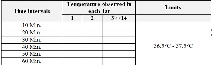
6.6.2 Calibration of Temperature check:
6.6.2.1 Fill 900 ml of purified water in each dissolution vessel. Set the temperature of the bath to 37.0°C. Start the spindle at 50 RPM and allow the instruments to achieve the set temperature. Once the instrument displays are ready. Record the temperature in all the jars and confirm the set temperature after 10, 20, 30, 40, 50, and 60 minutes time with calibrated temperature logger/thermometer.
Acceptance criteria: The observed temperature of each jar should be between 36.5°C to 37.5°C.
6.6.3 Calibration of Timer :
6.6.3.1 Adjust the “SET TIME” to 30 minutes. Press the start button and simultaneously start the stopwatch. When the system starts producing an alarm, check the time on a calibrated stopwatch. Follow the procedure for 60 minutes as above :
Acceptance Criteria:
| Set Time | Tolerance |
| 30 minutes | Between 29 minutes 24 seconds and 30 minutes 36 seconds. |
| 60 minutes | Between 58 minutes 48 seconds and 61 minutes 12 seconds. |
The procedure of Wobble Check:
6.6.3.2 Check the calibration for wobble for paddles and baskets using calibrated wobble meter. Empty all the jars and keep them in their respective positions. Lower the stirrer unit down so that the blades of the paddle/baskets enter the jars. Ensure that the paddle or basket rod is properly tightened with the spindle, use the key provided to tighten it. Fix the wobble meter in the stand and attach it to the jar in such a way that the sensor of the dial gauge is just touching the body of the paddle without any obstruction.
6.6.3.3 Start the rotation of the paddle/basket rod. Check the maximum deviation of the pointer of a device on both sides of ‘0’ and add the reading, carry out this procedure for 50 and 100 rpm, and measure the wobble (in mm) from dial gauge. Check for all eight paddles/baskets.
Acceptance criteria: The tolerance for wobble is not more than 0.5 mm for paddles and 1 mm for baskets. Check the wobble of all 8 paddles and baskets.
6.6.4 Measurement of Distance from Paddle to Bottom of Jar :
6.6.4.1 Keep all the jars empty. Clamp all the jars using jar holder provided on jar plate and lower the stirrer unit to the bottom most position till it stops automatically. Hold the depth gauge apparatus vertical or calibrated vernier caliper and touch parallel to the paddle shaft. Touch the reference bracket of the depth gauge apparatus or vernier caliper at the bottom face of the paddle. Slide the depth gauge apparatus or vernier caliper scale down till the point of the stylus touches the jar bottom. Lock the depth gauge apparatus or vernier caliper at this position and note the reading. Repeat the procedure for the remaining seven paddles.
Acceptance Criteria: The distance should be 25 mm ±2 mm.
6.6.5 Measurement of distance from basket to bottom of jar and the total height of basket :
6.6.5.1 Follow the same procedure given in the measurement of distance from paddle to bottom of jar using a basket instead of a paddle.
Acceptance Criteria: The distance should be 25 mm ±2 mm and the total height of the basket should be 37 mm ±0.3 mm.
6.6.6 Centering of shaft :
6.6.6.1 Measured by calibrated Vernier caliper. Measure Inner Diameter of a vessel.
6.6.6.2 Measure Diameter of shaft. The shaft should rotate at center of axis of the vessel = 46 mm (approx.) from inner wall of the vessel (considering the 10 mm thickness of the shaft, its surface should be about 46 mm from the inner wall of the vessel.
6.6.6.3 Permissible tolerance = ±2 mm.
| Vessel No. | Left Side of Vessel | Right Side of Vessel | Front Side of Vessel | Back Side of Vessel |
| 1 | ||||
| 2 | ||||
| 3 | ||||
| 4 | ||||
| 5 | ||||
| 6 | ||||
| 7 |
6.6.7 Distance between the shaft axis and vertical axis of the vessels :
6.6.7.1 Empty all the jars. Lower the stirrer unit down so that the blades of the paddle enter the jars.
6.6.7.2 Fix the wobble meter on the jar so that the pointer is just pressed against the paddle shaft.
6.6.7.3 Rotate the device with both hands around the shaft of the paddle in the jar. Ensure that the bottom plate is not lifted from the jar or it is in contact with the jar properly.
6.6.7.4 Make a note of the deflection of the pointer on both sides of ‘0’. Add both readings and divide the sum by two.
Acceptance Criteria: Centering should be <2 mm.
6.6.8 Integrity checks of the basket :
6.6.8.1 Check the integrity of SS wire mesh by holding the basket under the illuminated magnifier and visually check for any damages.
6.6.8.2 Repeat the procedure for the remaining baskets.
Acceptance Criteria: The mesh should be intact. (In case of SS wire mesh is found to be damaged, discard the basket).
6.7 Calibration {(Chemical Parameters) [Frequency : 6 Months]} :
For chemical calibration of dissolution apparatus:
6.7.1 Prednisone Tablets 10 mg:
6.7.1.1 On storage these tablets may stick to each other, or gentle pressure or tapping of the bottle may be used to separate them. Cracked, chipped, and capped tablets should not be used. However, tablets with minor surface flaws are generally acceptable for use. Powders on the surface of tablets should be removed prior to use. If equipment is dedicated for use with only one apparatus (basket or paddle), then calibration is not required for both apparatus. A membrane filtering method shall be used for the filter and the first 2 ml of solution should be discarded.
6.7.2 Procedure:
6.7.2.1 Check the current Lot No. of tablets with calibration of dissolution apparatus as per USP.
6.7.2.2 Fill 500 ml of deaerated water in each bowl and maintain the temperature at 36.5 to 37.5°C.
6.7.2.3 Set a timer for 30 minutes, speed 50 RPM.
6.7.2.4 Mount Apparatus-I (Basket) and put one tablet in each.
6.7.2.5 Run the instrument for a set time.
6.7.2.6 Draw a 10 ml sample for measure reading.
6.7.2.7 Prepare standard: weigh accurately about 20 mg of Prednisone RS add 10 ml of Alcohol to dissolve, dilute with water to make 100 ml, and further dilute 5 ml solution to 50 ml with water. To get the concentration of 0.02 mg/ml.
6.7.2.8 Preparation of sample: Pipette 10 ml of sample solution from each jar at the above-mentioned interval, and filter through a 0.45-micron nylon syringe.
6.7.2.9 Read the absorbance of the standard solution and dissolution test solution at about
242 nm. Repeat steps 5 to 7 with apparatus II (paddle) at a speed of 50 RPM.
6.7.2.10 Fill in the format and calculate the percentage of drugs released.
Acceptance Criteria: %age release as given in the COA of a particular lot.
6.7.2.11 After completing the calibration if the calibration results are satisfactory affix a calibration tag having details like instrument name, instrument ID number, calibration is done on, and calibration due on and done by.
6.7.2.12 If calibration results are not satisfied immediately paste the label “Out of calibration, Do not use” on the instrument.
6.7.2.13 Record the data in the dissolution apparatus logbook.
7.0 Abbreviations
AD: Analytical Development
RPM: Rotations per minute.
USP: United State Pharmacopoeia.
RS: Reference solution.
AC: Alternate current.
SS: Stainless steel
LED: Light Emitting Diode.
COA: Certificate of Analysis.
8.0 References:
8.1 Manufacturers Operating Manual.
8.2 United State pharmacopeia.
8.3 In-House.
9.0 Annexure:
9.1 ANNEXURE-I: Log Book of Dissolution Apparatus.
9.2 ANNEXURE-II: Physical Calibration Record of Dissolution Apparatus.
9.3 ANNEXURE-III: Chemical Calibration Record of Dissolution Apparatus.
Note: The annexure and calibration of dissolution apparatus PDF will be uploaded shortly.

Pankaj Sharma — Quality Control Specialist
Pankaj Sharma is a pharmaceutical QC professional who reviews our technical content for GMP accuracy, laboratory practices, and regulatory relevance.