1.0 Purpose: To describe the procedure for operation and cleaning of mobile SIP unit
2.0 Aim: This Standard Operating Procedure is applicable for the operation and cleaning of mobile SIP unit.
3.0 Responsibility: 3.1 The operator is responsible for operation and cleaning as per SOP.
3.2 Officer/Executive shall supervise the process.
3.3 Production manager for implementation of SOP.
3.4 Head QA shall be responsible for compliance with SOP
4.0 Precautions:
4.1 Check out for leakage during the process and tighten the valves.
4.2 Ensure that all the utilities are available.
4.3 Wear safety goggles during operation.
4.4 During any emergency press the emergency button on the main supply control panel to stop the process.
5.0 Equipment:
5.1 Solution preparation area:- (includes the list of equipment with I.D)
6.0 Materials and reagents:
6.1 Hose pipes with TC clamps.
6.2 Silicon tubing with TC clamps.
6.3 Lint-free duster
6.4 70% IPA.
7.0 Procedure:
7.1 Pre-checks before starting the system:-
7.1.1 Compress air supply should be available at 6 bars pressure
7.1.2 Pure steam should be available at mentioned pressure & Temperature with range.
7.1.3 Panel power must be ‘ON’. There are lamps on the panel, which indicate the phase incoming supply to the panel. These lamps must be ‘ON’.
7.1.4 Mains supply switch located at the side of the panel must be ‘ON’.
7.1.5 All MCBs / MPCBs inside the panel must be ‘ON’.
7.1.6 Emergency stop button must be released. If not then release it.
7.2 Cleaning:-
7.2.1 Put the SIP unit to switch ‘OFF’.
7.2.2 Dry mop the outer surface of the SIP unit using a clean lint-free duster.
7.2.3 Thereafter, mop the outer surface of the SIP unit with a clean lint-free duster soaked in 70% IPA.
7.2.4 Switch the SIP unit ‘ON ’
7.2.5 Allow the SIP unit to dry for a while.
7.2.6 Clean the steam traps after the use of the SIP unit.
7.2.7 Attach the ‘CLEANED / READY FOR USE’ status label on the SIP unit.
7.3 Operation:-
7.3.1 First of all switch ‘ON’ the SIP unit.
7.3.2 Enter the password.
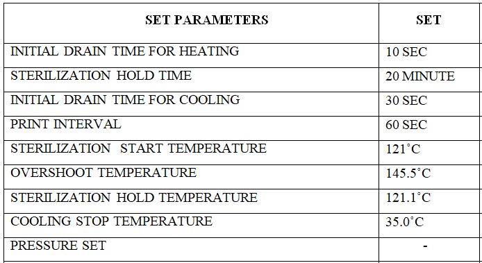
7.3.3 Press the set parameter button as per Annexure 1 attached for sampling port sterilization in the SIP unit.
7.3.4 Press the ‘PRINT’ button to switch ‘ON’ the printer of the SIP unit.
Note: Press the toggle button to display “PRINT ENABLE”.
7.3.5 Connect the SIP unit to the sampling port with a hose pipe and silicon tubing.
7.3.6 Press the ‘PROCESS MODE’ button to enter the process mode menu.
7.3.7 start the sampling port SIP.
7.3.8 Press the ‘START’ button on the SIP unit to start the SIP of the sampling port.
7.3.9 After completion of sterilization hold, Cooling starts.
7.3.10 When the cooling temperature is achieved, disconnect the silicon tubing aseptically from the sampling port under Mobile LAF (horizontal inclinable) and close the side air manual valve.
7.3.11 Stop the process of SIP on the SIP unit.
7.3.12 Connect the vent filter to the sampling port aseptically under LAF.
8.0 Abbreviations:
SOP: Standard operating procedure
LAF: Laminar air flow
IPA: Isopropyl alcohol
SIP: Sterilization in place
MCB/MPCB: Miniature circuit breaker/ Motor protection circuit breaker
PR: Production
QC: Quality Control
Annexure-I

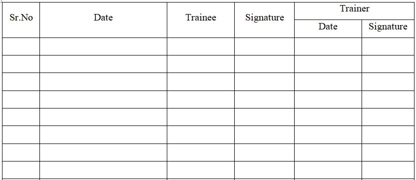
Annexure-II


Naresh Bhakar is the Founder and Author at Pharmaguddu.com, bringing his extensive expertise in the field of pharmaceuticals to readers worldwide. He has experience in Pharma manufacturing and has worked with top Pharmaceuticals. He has rich knowledge and provides valuable insights and data through his articles and content on Pharmaguddu.com. For further inquiries or collaborations, please don’t hesitate to reach out via email at [email protected].
