
Here learn about the complete process of Auto Coater Installation Qualification along with Annexures, criteria, approval, final report, and conclusion.
Download Auto Coater Installation Qualification PDF file, The Link is Given Below
| ITEM DESCRIPTION |
| PROTOCOL APPROVAL |
| OVERVIEW: |
| Objective |
| Purpose |
| Scope |
| Responsibility |
| Execution Team |
| ACCEPTANCE CRITERIA |
| REVALIDATION |
| INSTALLATION QUALIFICATION PROCEDURE |
| System Description |
| Instruction for Filling the Checklist |
| Installation Check-List |
| Identification of Major Components |
| Verification of material of construction |
| Identification of Supporting Utilities. |
| Identification of Safety Feature(s) |
| Identification of Standard Operating Procedure |
| Test instrument details |
| Identification of Component to be Calibrated |
| Verification of Drawings and Documents |
| Abbreviations |
| Deficiency And Corrective Action(s) Report(s) |
| Annexure(s) |
| INSTALLATION QUALIFICATION FINAL REPORT |
| Summary |
| Conclusion |
| Final report approval |
| 1.0 | PROTOCOL APPROVAL: |
The signing of this approval page of the Protocol indicates agreement with the qualification approach described in this document. If a modification to the qualification approach becomes necessary, an addendum shall be prepared and approved. The protocol cannot be used for execution unless approved by the following authorities.
This Installation Qualification protocol of Auto Coater has been reviewed and approved by the following persons:
| FUNCTION | NAME | DEPARTMENT | SIGNATURE | DATE |
| PREPARED BY | QUALITY ASSURANCE | |||
| REVIEWED BY | PROJECTS / ENGINEERING | |||
| REVIEWED BY | PRODUCTION | |||
| APPROVED BY | QUALITY ASSURANCE |
2.0 | OVERVIEW: |
| 2.1 | OBJECTIVE: |
| The objective of developing and executing this protocol is to collect sufficient data about the Auto Coater and define the installation qualification requirements and acceptance criteria for the Auto Coater. Successful completion of these installation qualification requirements will ensure that the Auto Coater was installed as required in the manufacturing area. | |
| 2.2 | PURPOSE: |
| The purpose of this protocol is to establish documentary evidence to ensure that the Auto Coater system received matches the Design specification and also to ensure that it is properly and safely installed. | |
| 2.3 | SCOPE: |
| This Protocol applies to the installation of Auto Coater at the tablet manufacturing facility at (Company Name) & the subsequent documentation. | |
| 2.4 | RESPONSIBILITY: |
| The following shall be responsible: Quality Assurance officer/ Executive – Preparation of protocol projects / Engineering Head – For execution Production Head – For execution support Quality Assurance Head – For adequacy and final approval |
| 2.5 | EXECUTION TEAM: |
| The satisfactory installation of the (Company Name) Auto Coater shall be verified by executing the qualification studies described in this protocol. The successfully executed protocol documents that the Auto Coater is installed satisfactorily. The execution team is responsible for the execution installation of Auto Coater Execution team comprises of: |
| DEPARTMENT | DESIGNATION | NAME | SIGNATURE | DATE |
| PROJECTS/ ENGINEERING | ||||
| PRODUCTION | ||||
| QUALITY ASSURANCE |
3.0 | ACCEPTANCE CRITERIA: |
| 3.1 | The Auto Coater shall meet the system description given in the design qualification. |
| 3.2 | The Auto Coater shall meet the acceptance criteria mentioned under the topic “Identification of major components” |
| 3.3 | The Auto Coater system shall be operated by PLC. |
| 4.0 | REVALIDATION CRITERIA: |
| The Auto Coater has to be revalidated if… | |
| Any major changes in system components affect the performance of the system· After a major breakdown maintenance is carried out. As per the revalidation date and schedule. |
| 5.0 | INSTALLATION QUALIFICATION PROCEDURE: |
| 5.1 | AUTO COATER (Version Name) SYSTEM DESCRIPTION: | ||
Process Equipment Description
The purpose of (Company Name) Auto Coating Machine (Version Name) is to coat tablets of all common sizes and shapes whether it is for film or aqueous coating. The hot air in this equipment will enable a very efficient heat and mass transfer. The hot air flow is controlled by PLC and is programmable to accommodate various types of tablets and their coating materials.
The complete machine can be divided into the following sub-sections:
- Inlet System
- Pan
- Spray System
- PLC System
- Cleaning system
- Exhaust System
- Control System
Inlet System: It consists of pre & medium air filters, HEPA filters (Optional), air heating unit, and airflow & temperature measuring devices. The inlet air handling unit (Inverter control) receives air from the environment and processes the inlet air and controls the inlet airflow.
Pan: It consists of the semi-perforated fully enclosed pan which contains 8 ducts that engage with the incoming air and the outgoing air through arc shaped inlet duct from the heat exchanger and outlet duct that goes to the exhaust. At any point in time, two circular cross-sectional areas of the pan engage with the hot air inlet and outlet.
Spray System. It consists of a peristaltic pump in case of film coating. This pump is selected based on the viscosity of the solution that has to be coated. This pump is eventually connected to the tubing that leads to high-pressure low-volume guns. The angle of the spray and the flow rate are externally controllable.
A programmable logic controller (PLC) will execute the direction of the sequence of operations. The PLC of (Brand Name) (or equivalent) is used for this purpose.
5.2 PLC Description
The main function of a PLC is to translate the instructions into the digital or analog codes needed to operate the device or machine.
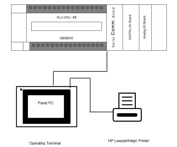
PLC collects data from field instrumentation & displays the information on the operator station. The instruments are connected to the system equipment and piping. The PLC will utilize the collected data for process control.
The user interface, based on an industrial-type HMI, will assist the operator to supervise and control the process. Based on the displayed information the operator, using the user interface, can provide commands to the PLC.
The PLC then executes the operator’s instructions. A (Brand Name) has been chosen as the Central Processing Unit (CPU). There are six inner boards available, which are mounted in Slot 1 or Slot 2 of a (Serial Number). The protocols are made on the XYZ – Protocol Support Software and then recorded in the Serial Communication Board, where they can be executed at any time using the PMCR instruction in the CPU unit’s ladder diagram.
The PLC system layout for the coating machine automation is as shown below:
| 5.2 | INSTRUCTION FOR FILLING THE CHECKLIST |
| 5.2.1 | In case of compliance with the test use the word ‘Complies’ otherwise use ‘Does not comply‘ to indicate non-compliance. |
| 5.2.2 | For identification of the components of the equipment and utilities use the word ‘’yes’’ to show its presence and use ‘No’ to indicate the absence of the identity |
| 5.2.3 | Give detailed information in the summary and conclusion part of the Installation Qualification report. |
| 5.2.4 | Whichever column is blank or not used ‘NA’ shall be used. |
| 5.3 | INSTALLATION CHECKLIST: |
| The installation checklist is as follows: |
| Sr.NO. | STATEMENT | YES / NO | CHECKED BY(SIGN) | DATE |
| Verify that the “As Built” drawing is complete and represents the design concept. | ||||
| Verify that major components are securely anchored and shockproof. | ||||
| Verify that there is no observable physical damage. | ||||
| Verify that there is sufficient room provided for servicing. | ||||
| Verify that all piping and electrical connections are done according to the drawings. | ||||
| All access ports are examined and cleared of any debris. | ||||
| Safe electrical connections. | ||||
| Sufficient room is provided for maintenance. | ||||
| The equipment identification nameplate is visible. | ||||
| Units installed on the foundation are secure as per the manufacturer’s recommendations. |
| 5.4 | IDENTIFICATION OF MAJOR COMPONENTS: |
| Describe each critical component and check them and fill out the inspection checklist. |
| System Components | Design Specification | Complies / Does Not Comply | Checked By(Sign) | Date | |
| 1. Equipment Description | Model | XYZ | |||
| Output Capacity | 120 – 150 Kg (Put Value) | ||||
| Power of the Main motor | 3.7KW (Put Value) | ||||
| Hot water Pressure | 3 Kg/cm sq. | ||||
| Volume of Heating | 42000 KCal (Put Value) | ||||
| 2. Pan | Pan diameter | 1300mm (Put Value) | |||
| Material | SS 316L | ||||
| Spray Sliding Cylinder | SS 304 | ||||
| Rabbit Ear Baffles | 7 Nos. (Put Value) | ||||
| Pan Motor | 3 HP (Put Value) | ||||
| Pan speed | 1 – 12 RPM (Put Value) | ||||
| 3. Solution Tank | Capacity | 100 L (Put Value) | |||
| Material of construction | SS316L | ||||
| Manufacturing Design | Casters mounted. | ||||
| 4. Air Device Rating | Main Air Regulator | 0~10 Kg/cm sq. | |||
| Atom Air Regulator | 0~10 Kg/cm sq. | ||||
| Spray Gun Air Regulator | 0~10 Kg/cm sq. | ||||
| Air Pump Regulator | 0~10 Kg/cm sq. | ||||
| Main Pressure Gauge | 0~10 Kg/cm sq. | ||||
| Air Flow Meter | 0~500 Lit/min. | ||||
| Manometer | 0~500 mm Aq | ||||
| 5. Pump | Manufacturer | XYZ | |||
| Model | Modal Name | ||||
| RPM | Max 220 (Put Value) | ||||
| Shaft Torque | 2.2 Nm | ||||
| 6. Other Components | Touch Screen | XYZ | |||
| Proximity switches | Autonics Corporation | ||||
| Flowmeter | XYZ | ||||
| Magnehelic Differential pressure gauge | XYZ | ||||
| Solenoid Valve | TPC Pneumatics | ||||
| VFD | XYZ | ||||
| 7. Spray Gun | Manufacturer | XYZ | |||
| Model | Modal Name | ||||
| 8. Exhaust Blower Air Fan Motor | Manufacturer | XYZ | |||
| Speed Controller | XYZ VFC | ||||
| Filter | Polyester filter bag with an auto-shaking function | ||||
| 9. Operating Control Panel | PLC Make | XYZ | |||
| PLC Model | XYZ | ||||
| PLC CPU | CPU 44 (Put Value) | ||||
5.5 | Verification of Material of construction: |
| Sr. No. | Name of components | Material of construction | Method of verification | Verified by(Sign & Date) |
| 1 | Rotary Inlet Outlet Valve | SS 41 | ||
| 2 | Outside Door | SS304 | ||
| 3 | Outside Cover | SS304 | ||
| 4 | Pan Door | SS316 & Strengthened Glass | ||
| 5 | Auto damper | SS304 | ||
| 6 | Coating Pan | SS316 | ||
| 7 | Film Tank | SS 316 | ||
| 8 | Coating Door | SS 304 | ||
| 9 | Machine Body | Frame: SS41, Cover: SS 304 | ||
| 10 | Liquid Tank Flange | SS304 | ||
| 11 | Tank Top Cover | SS304 | ||
| 12 | Liquid Tank | SS316 | ||
| 13 | Liquid Tank Oil Seal Cover | SS304 | ||
| 14 | Liquid Tank Impeller shaft coupling | SS304 |
5.6 | IDENTIFICATION OF SUPPORTING UTILITIES: |
| UTILITY | PROPERLY IDENTIFIED & CONNECTED (YES/NO) | CHECKED BY (SIGN) | DATE |
| 1) Electricity: 3 Phase, 415Volts, 50Hz | |||
| 2) Compressed air: 6 kg/cm2 12 mm, 500 L/min | |||
| 3) Hot water 65000Kcal/Hr, 2Kg/cm2 |
5.7 | IDENTIFICATION OF SAFETY FEATURES: | |||||||
| Identify and record the safety features (if any) and their function in the following tables: | ||||||||
| Safety Features Description | Function | Identified By(Sign) | Date | |||||
| Earthing | To avoid electrical shocks due to leakage current. | |||||||
| Alarm Message | ||||||||
| 1. Purging Air Pressure Low | If the air pressure drops below the minimum set level, then this alarm will trip the machine. | . | ||||||
| 2. Machine Stoppage | If the emergency stop is operated the alarm will generate | |||||||
| 3. Main Motor Overload | If the Sharft motor is overloaded the alarm will generate and trip the process | |||||||
| 5.8 | IDENTIFICATION OF STANDARD OPERATING PROCEDURE (SOP) | ||||||
| The following Standard Operating Procedures were identified as important for the effective performance of Auto Coater | |||||||
| 1 | Operation and cleaning of Auto Coater | ||||||
| 2 | Preventive maintenance of Auto Coater | ||||||
5.9 | TEST INSTRUMENT DETAILS |
| Instrument/Equipment required: 1. Tacho Meter 2. Anemometer 3. Temperature sensor 4.Pressure Gauge 5. Photometer |
| 5.10 | IDENTIFICATION OF COMPONENT TO BE CALIBRATED |
| In the Auto Coater, the following are the components, which need calibration. The following are the components: 1. Pressure Measurement (Purging Air) 2. Temperature Measurement 3. R.P.M. | |
5.11 | VERIFICATION OF DRAWING AND DOCUMENTS: |
| The following documents are reviewed and attached below: (Fill Your Details Below) |
| Sr. No. | DRAWING AND DOCUMENT DETAIL | CHECKED BY (SIGN) | DATE |
5.12 | ABBREVIATIONS |
| The following Abbreviations are used in the installation qualification protocol of the Air handling unit | |
| MOC: Material of construction RPM: Rotation per minute Nm: Neuton meter PLC: Programming Logic Controller ACT: Auto Coater |
| 5.13 | DEFICIENCY AND CORRECTIVE ACTION (S) REPORT (S) |
| The following deficiency was identified and corrective actions were taken in consultation with the validation team. | |
| Description of deficiency: |
| Corrective action(s) taken: |
Reviewed By:
Date
5.14 Annexure(s):
| Sr. No. | Annexure No. | Title of Annexure |
| 6.0 | INSTALLATION QUALIFICATION FINAL REPORT: |
| All the IQ data sheets and discrepancy reports shall be reviewed by the validation team to prepare a summary report. The summary of IQ shall be used to conclude approval of the installation qualification report. |
| 6.1 | SUMMARY |
| 6.2 | CONCLUSION |
6.3 FINAL REPORT APPROVAL
It has been verified that all tests required by this protocol are completed, reconciled, and attached to this protocol or included in the qualification summary report. Verified that all amendments and discrepancies are documented, approved, and attached to this protocol.
The signature in the block below indicates that all items in this qualification report of Auto Coater (Modal) have been reviewed and found to be acceptable and that all variations or discrepancies have been satisfactorily resolved.
| NAME | DESIGNATION | DEPARTMENT | SIGNATURE | DATE |
| PROJECTS / ENGINEERING | ||||
| PRODUCTION | ||||
| QUALITY ASSURANCE |
Read: Design Qualification of Electric Stacker
Design Qualification Protocol for Vertical Laminar Reverse Flow
Installation Qualification Protocol for Autocoater PDF- Download
-
by
-