
GMP & Pharmaceutical Manufacturing Expert
✓ Reviewed by: Pankaj Sharma - Quality Control Specialist
Reviewed for Quality Control accuracy, laboratory practices, analytical methods, and technical relevance
📅 Last Updated: May 11, 2026
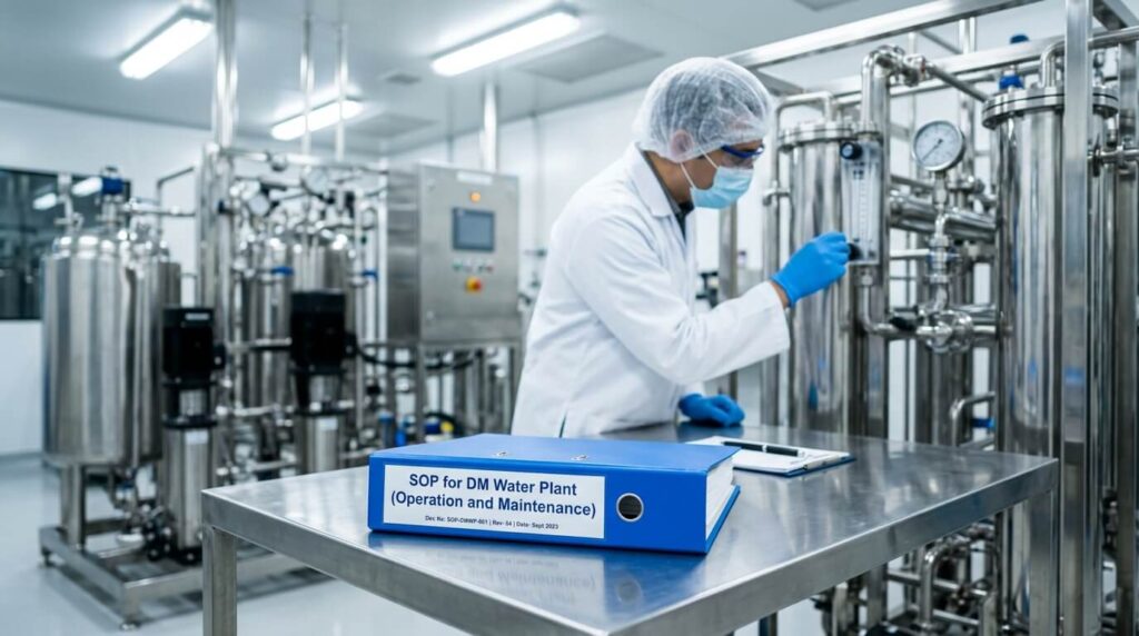
1.0 OBJECTIVE: To lay down the procedure for operation and maintenance of DM water plant.
2.0 SCOPE: This procedure applies to DM water plant in Pharmaceuticals.
3.0 RESPONSIBILITY: Production In-Charge, Maintenance personnel, Maintenance Engineer.
Learn: SOP for Preventive Maintenance of DM Plant
4.0 PROCEDURE for DM Water Plant:
4.1 PLANT SPECIFICATIONS:
Maximum flow rate: 1.2 m3 / hr
Output between regeneration: 30 m3
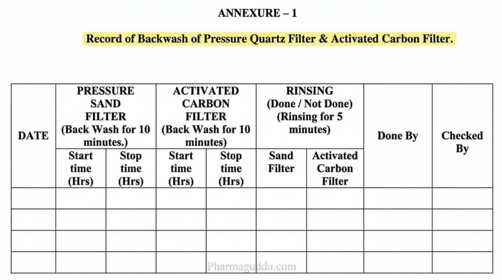
Before starting the D. M. plant, carry out the ‘back-wash’ of the Pressure Quartz filter & Activated Carbon filter. Carry out the back wash procedure on each working day before starting the plant (As per Annexure I ).
4.2 BACKWASHING OF PRESSURE QUARTZ FILTER: (Sand Filter)
4.2.1 Ensure that the raw water feed pump “P1” is put “OFF”.
4.2.2 Set the multi-port valve of Quartz Filter “QV1” in ‘back–wash’ mode.
4.2.3 Switch “ON” the feed pump “P1”. Continue the backwash for 10 minutes or till clear water is obtained at the outlet of the vessel. Allow all the water from the outlet to be drained off.
4.2.4 Do the backwashing at the beginning of each production day.
4.2.5 After completing the backwash, put “OFF” the pump “P1” and set multi port valve “QV1” in operation mode (filter position).
4.2.6 Carry out backwash for prolonged time (30minutes) once a week for better cleaning.
4.3 BACKWASH OF ACTIVATED CARBON FILTER:
4.3.1 Switch “OFF” the raw water feed pump “P1” and set multiport valve of the Carbon Filter “CV1” in backwash position.
4.3.2 Start the pump “P1” and allow water from outlet to be drained off. Continue the back wash for 10 minutes or till clear water is obtained at the outlet of the vessel.
4.3.3 After the backwash, put “OFF” the feed pump “P1” and set the multiport valve “CV1” to filter position.
4.3.4 Do the backwash at the beginning of each production day.
4.3.5 Carry out the backwash for prolonged time (30 minutes) once a week for better cleaning.
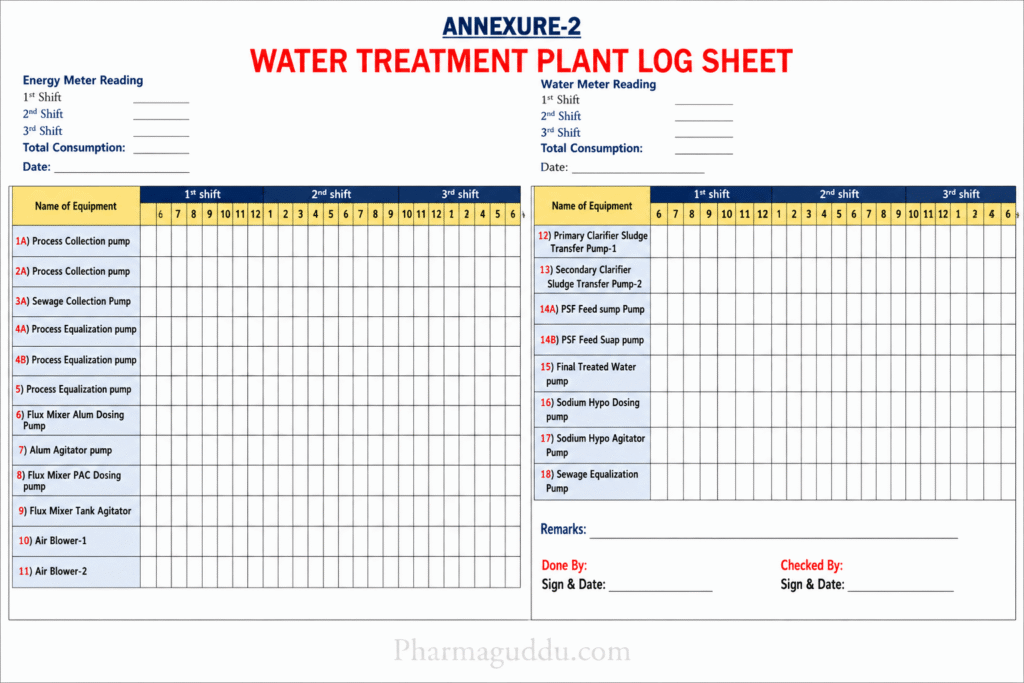
4.4 STARTING THE UNIT: ( As per Annexure II )
4.4.1 Before starting the unit, ensure that the RO reject control valve “RV1” is fully open.
4.4.2 Switch “ON” the raw water feed pump “P1” Ensure that the multiport valve of the softener “SV1” is in service mode & Inlet Isolation valve of softener (Suctionvalve) “SV2” is in closed position & valves on feed line after 5Micron filter before & after Pump P2–“P2V1” & “ P2V2” are in open position & valve for sampling of water for test of hardness of softener outlet water SV3 is in closed position.
4.4.3 Allow the air in the system to be purged through activated carbon filter & Softener by opening the air release device of the Carbon Filter & also the inlet Isolation valve of Softener “SV2” for a short time till all the air in the system is released. Close the air release device of carbon filter & the suction valve“SV2” of the softener.
4.4.4 Allow the pressure of water at the R.O. unit feed line to rise. When it reaches about 2-3kg/cm², as indicated by the pressure gauge “PG4”on the feed line, start the R.O Pump “P2” & the dosing pump “DP1” & ensure that the R.O. discharge valve “RV1” is open.
4.4.5 Maintain the pressure at about 2-3 kg/cm². When the water enters the R.O. unit & exits through the rejection valve RV1”, throttle the R.O. reject control valve “RV1” so as to obtain desired performance – permeate flow of about 1.2 m3/hr & reject flow of about 0.8 m3/hr as indicated by the respective rotameters “RM1” & “RM2”. Never close the reject control valve “RV1” fully as it would harm the membranes permanently. Raw water flows from under ground tank through sand filter, carbon filter, softner, a 5-micron filter, R.O units & into the R.O. water storage tank through Rotameter “RM1”. RO reject water will flow through reject control valve “RV1” & Rotameter “RM2” into the drain. Ensure RO Tank Drain valve “RV2” is in closed position & valves before & after Pump P3 “P3V1” & “P3V2” are in open position.
4.4.6 The dosing pump “DP1” pumps the dosing solution (Antiscalent solution) from the dosing tank into the system.
4.5 PREPARATION OF DOSING SOLUTIONS:
4.5.1 The dosing solution for the RO unit is prepared by adding 1 liter of ZLS 405 liquid in 50 Liters of purified water in a tank.
4.6 When sufficient water has collected in the R.O. storage tank (about ¾th level of the tank), start the D.M. feed pump “P3” Switch “ON” both the UV lamps “UV1” & UV2” & the three conductivity meters Water will now flow from R.O storage tank through Rotameter “RM3” into the strong acidic cation exchanger (SAC)strong base anion (SBA) exchanger, UV lamp 1, Mixed bed “MB”, UV lamp 2,1Micron cartridge filter & water meter & finally into the main storage tank (500Liters). Ensure that the valve going from 1Micron filter “CF2V1” to water meter is open & valve going into recirculation Sintex Tank “CF2V2” is in closed position Ensure multiport valves of Strong Acid Cation “SACV1”, Strong base Anion “SBAV1” are in up flow positions & that of Mixed bed “MBV1” is in filter position & valve on line going in to strong acid cation from pump P4 “P4V1” is in closed position.
4.7 The three conductivity meters are
4.7.1 CM1: RO Water (Conductivity Limit 20 to 50 Microsiemens/cm)
4.7.2 CM2: Strong base Anion (SBA) Water ( Conductivity Limit 0 to 20Microsiemens /cm.)
4.7.3 CM3: DM water after mixed bed (Conductivity Limit 0 to 1.0 Microsiemens / cm.)
4.7.4 To measure the conductivity in each case, open the outlet drain valves attached to the respective meter connections “CM1V1” for RO Water, “CM2V1” for anion water, and “CM3V1” for DM water – allow the water to drain for sometime for the conductivity readings to stabilize.
4.8 SHUT DOWN OF THE PLANT:
4.8.1 Before shutting down the plant, keep the rejection valve “RV1” fully open.
4.8.2 Switch “OFF” the R.O. feed pump “P2”. Let all the water get drained out of the R.O. unit through RO discharge valve “RV1.”
4.8.3 Switch “OFF” the raw water feed pump “P1” & then the D.M. feed pump “P3” as well as the dosing pump “DP1”& UV lamps “UV1”& “UV2” & the three conductivity meters “CM1”, “CM2” & “CM3” & close valve “CM1V1”, CM2V1”, & “CM3V1”.
4.8.4 Pressure Gauges are placed at the following points:
PG1: Sand Filter Outlet.
PG2: Carbon Filter Outlet.
PG3: Softner Outlet.
PG4: 5 Micron Filter Outlet.
PG5: RO Pump Outlet.
PG6: RO Discharge Outlet.
PG7: Mixed Bed Outlet.
4.9 REGENERATION & RINSE OPERATION OF D.M. PLANT:
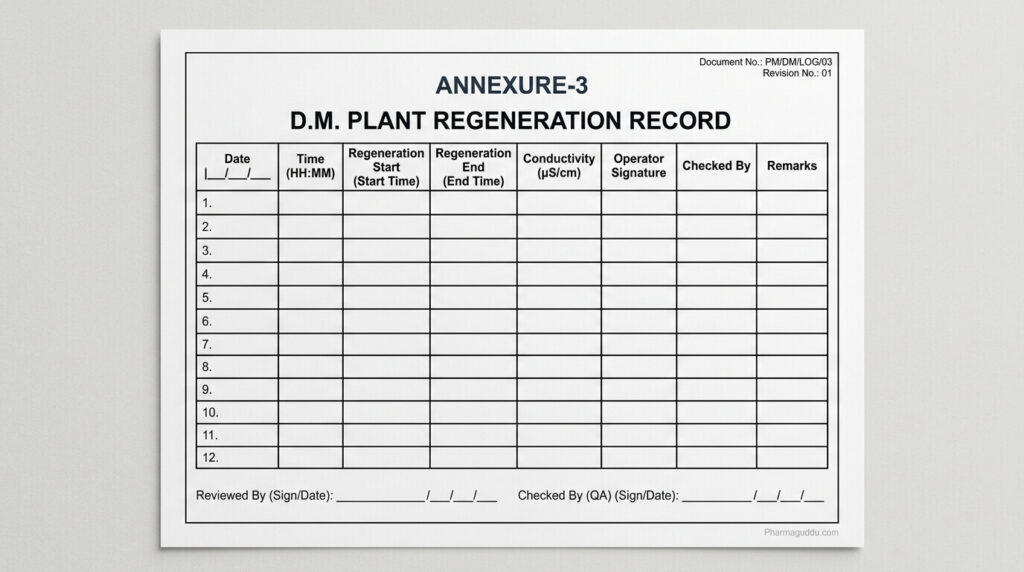
4.9.1 To be carried out whenever the pH of final purified water is beyond the limit (4.5 to 7) or whenever the conductivity of the final water is above 1microsiemens/cm or whenever the conductivity of water of strong base anion exchanger is above 20 microsiemens/cm or output of plant reaches 30,000 liters after previous regeneration (As per Annexure III)
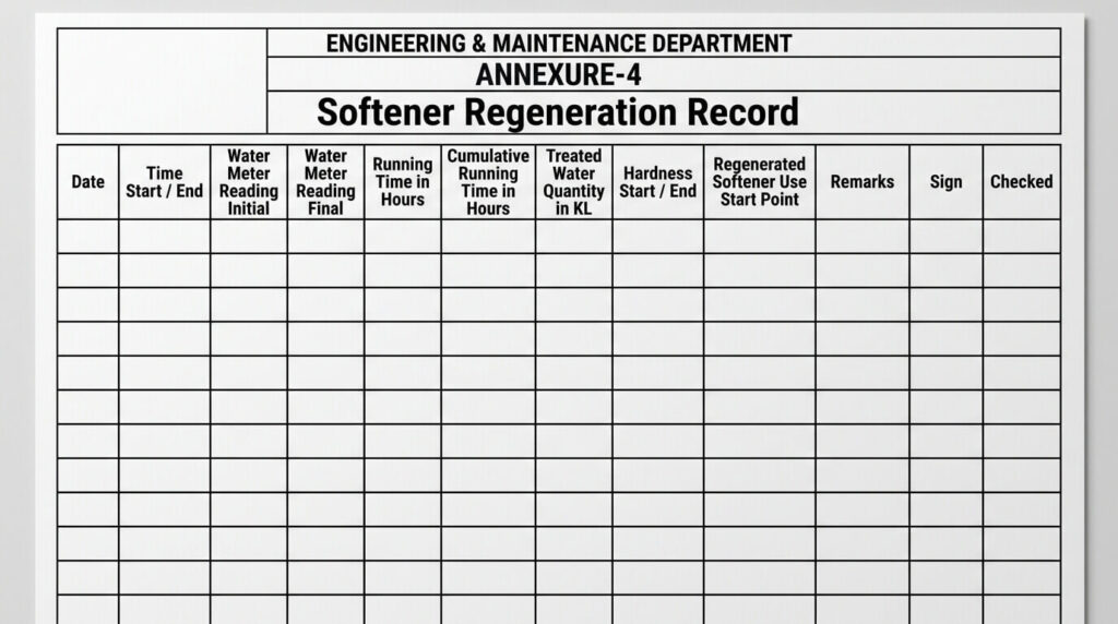
4.10 REGENERATION AND RINSE OPERATION OF SOFTENER:
4.10.1 To be carried out whenever hardness of softener outlet water is above 5ppm (as indicated by test for hardness detection), or conductivity of softener water is above 50 microsiemens / Cm. ( As per Annexure IV)
4.11 PREPARATION OF REGENERATION SOLUTIONS:
4.11.1 FOR STRONG ACID CATIONS: (SAC):
Prepare acid solution by taking 5.3 liters of HCl in 20 liters of filtered water in regeneration tank.
4.11.2 FOR STRONG BASE ANION (SBA):
Prepare alkali solution by taking 2.5 Kgs of NaOH in 20 liters of filtered water in regeneration tank.
4.11.3 FOR MIXED BED:
4.11.3.1 ACID SOLUTION PREPARATION: Prepare acid solution by taking 3.7 liters of HCl in 20 liters of filtered water in regeneration tank.
4.11.3.2 NaOH SOLUTION PREPARATION: Prepare alkali solution by taking 1.5 kgs of NaOH in 20 liters of filtered water in regeneration tank.
4.11.4 Prepare brine solution by taking 75Kg of sodium chloride in 300 liters of filtered water in regeneration tank.
4.12 CARRY OUT FIRST REGENERATION OPERATION AND THEN THE RINSE OPERATION IN EACH CASE AS FOLLOWS:
| PART | REGENERATION OPERATION | RINSE OPERATION | ||
| 1 | Strong acidic cation exchange. | Switch “OFF” the pump “P3” and set the multiport control valve “SACV1” in regeneration mode, insert the suction strainer in the regeneration tank containing regeneration solution. Switch “ON” the pump “P3”. Acid solution from regeneration tank is injected in cation exchanger by water ejector. After completion of injection of acid solution switch OFF the pump “P3”. | Switch “OFF” the pump “P3” and set the multiport control valve “SACV1” in rinse mode. Switch ON the pump “P3” and continue rinse operation for 15 minutes. Check pH of effluent water; it should be between 3–4, if not continue rinse operation for about another 10 minutes or more till the pH of effluent water is between 3 and 4. After operation is completed, set cation exchanger valve “SACV1” to normal operation (up flow) mode. | |
| 2 | Strong base anion exchanger. | Switch “OFF” the pump “P3” & set the multiport control valve “SBAV1” in regeneration mode, insert the suction strainer in the regeneration tank containing regeneration solution. Switch “ON” the pump “P3”. Alkali solution from regeneration tank is injected into the anion exchanger by a water ejector. After completion of injection of alkali solution, switch “OFF” the pump “P3”. | Switch “OFF” the pump “P3” & set the multiport control valve “SBAV1” in rinse mode. Switch “ON” the pump “P3” & continue rinse operation for 15minutes. Check pH of effluent water, it should be between 8–9.5, if not continue rinse operation for about another 10minutes or more till the pH is between 8 and 9.5. After operation is completed, switch off pump P3 & set anion exchanger multiport valve “SBAV1” to normal operation (Up Flow)mode. | |
| 3 | Mixed bed | Backwash Operation: Close inlet valve V2 & set multiport control valve “MBV1” in backwash mode. Open inlet valve V2 & backwash the unit for about 10minutes till cation & anion resins get separated. The distinct separation line should be seen in the lower glass inspection window. Close inlet valve V2 & open drain valve V7 to drain the water up to upper glass window. | Slow rinse: After completion of acid & alkali injection, close the valves V4 & V6, open valve V2 & set the multiport control valve “MBV1” in backwash mode. Switch “ON” the pump “P3” & rinse the mix bed for about 30minutes or more till pH of drain water is between 5.0 & 7.0 & then close all the valves. | |
# | PARTS | Check that the two distinct layers are formed. If not, continue backwashing until distinct separation is seen. Close valve V7. Simultaneous Regeneration Operation: Prepare the acid & caustic regeneration solutions as specified.Close inlet valve V2 & open valves V3,V4,V5,V6 & drain valve V7. Insert the suction strainers in regeneration tanks containing regeneration solutions. Acid solution is sucked through V4 & Caustic solution through V6 Start the D.M. Pump “P3”.After completion of acid & alkali injection, switch “OFF” the pump “P3”, keep multiport valve “MBV1” in backwash mode. Close valves V4 & V6. | Air Mixing Operation: Ensure multiport valve “MBV1” is in backwash mode. Open air inlet valve V8 & close all other valves & allow air to pass through resin bed for about 5 to 10Minutes.After complete mixing of resins, close the air inlet valve V8 & open drain valve V7 to drain the water from resin column. Fast Rinse: Close drain valve V 7, switch “OFF” the pump “P3” & set the multiport control valve “MBV1” in rinse mode. Switch “ON” the pump “P3” & open valve V2. rinse the mix bed unit until the pH of rinse water comes to 5–7.& conductivity comes below 1microsiemens/cm.Close valve V2& set control valve “MBV1” in service position.Open valve V2 to get D.M.Water at outlet of mixed bed unit & check the pH & conductivity. If not ok, continue the rinse operation till they are within limits. | |
| 4 | Softener: To be carried out whenever the total Hardness of the softener outlet water is above 5ppm. | Switch “OFF” the pump “P1” & close inlet isolation valve “SV2” & set the multiport control valve “SV1” in regeneration mode, insert the suction strainer in the regeneration tank & open valve “SV2”.Switch “ON” the pump “P1”. Brine solution from regeneration tank is injected into softner by water ejector. After completion of injection of brine solution, switch off the pump “P1” and close inlet isolation valve “SV2” of softner. | Slow rinse: Switch “OFF” the pump “P1”, close the inlet isolation valve “SV2” of softner & set the multiport control valve “SV1” in ‘slow rinse’ mode. Switch “ON” the pump “P1” Softner is slow rinsed for 15 minutes. Fast rinse: Switch “OFF” the pump “P1” and set the multiport control valve “SV1” in ‘fast rinse’ mode switch “ON” the pump “P1” & continue fast rinse operation for 20 minutes or more until the water in the drain is free of salt taste & Hardness & Conductivity are within limits After operation is completed, set the softner multiport valve “SV1” to normal operation (Service) mode. | |
4.13 TEST FOR DETECTION OF HARDNESS OF SOFTENER OUTLET WATER:
4.13.1 Take 50ml of water, which is to be tested in a sample by opening valve SV3.
4.13.2 Add 3 drops of reagents ‘A’.
4.13.3 Add 2 drops of reagents ‘B’.
4.13.4 The sample turns Violet.
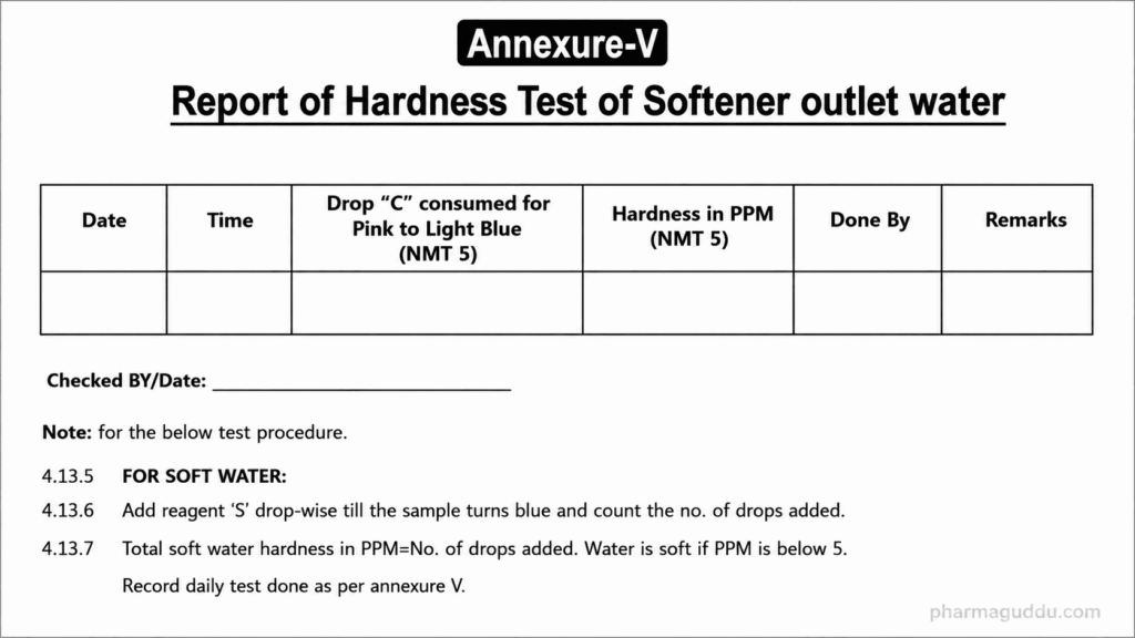
4.13.5 FOR SOFT WATER:
4.13.6 Add reagent ‘S’ drop-wise till the sample turns blue and count the no. of drops added.
4.13.7 Total soft water hardness in PPM=No. of drops added. Water is soft if PPM is below 5. Record daily test done as per annexure V.
4.14 MAINTENANCE:
4.14.1 Check at six-month intervals the internal condition of vessels, tank & fittings. Reline & renew material as & where required. Do not delay action when necessary.
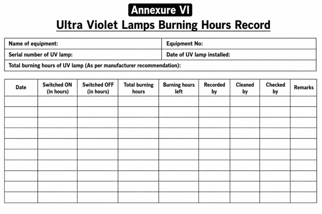
4.14.2 Change the UV lamps after 18 months & cartridge filters after every 6 months or whenever the final water does not comply with the microbial standards or the filters are choked. Maintain record of Burning hours of lamps (As per Annexure V I)
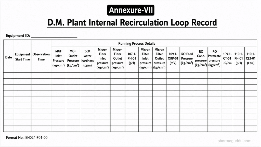
4.15 INTERNAL LOOP RECIRCULATION FOR D. M. PLANT:
4.15.1 Whenever the D. M plant is not in operation, collect purified water in a Sintex tank near the plant, which is connected by means of a pump “P4” into the cation exchanger.
4.15.2 Close the valves from R.O Outlet Tank “P3V1”&“P3V2” going in to Rotameter “RM3” & drain valves RV2 & open the valve “P4V1” from the above pump “P4” into the cation exchanger.
4.15.3 Close the outlet water pipe valve after the one 1µ cartridge filter going into the water meter “CF2V1” & open the valve of the pipeline from the 1µ cartridge filter going into the Sintex tank “CF2V2”.
4.15.4 Start the internal recirculation pump “P4”. Continue this circulation of water through the cationic exchanger, anion exchanger, UV light (1), mixed bed, UV light (2), and 1 micron filter into the Sintex tank, till the D. M. Plant is to be started again. Drain off the water from the Sintex tank when the D. M. Plant is started again.
4.15.5 When D.M. plant is started again, put off the internal circulation pump “P4”, close valve of outlet pipe from the Sintex tank going into cation exchanger “P4V1”, and open valve from the R.O. tank going into cation exchangers “P3V1” & “P3V2”.
4.15.6 Also, close the valve after 1 micron filter going into sintex tank “CF2V2” and open the valve going from 1 micron filter into water meter “CF2V1” and main D.M. water storage tank. ( As per Annexure VII)
4.16 EXTERNAL LOOP FOR THE PURIFIED WATER:
4.16.1 The purified water collected in the main storage 500-liter SS Tank is connected by means of a pump “P5” through a heat exchanger to the pipelines passing through all the users points in buildings No. X & Y..
4.16.2 This circulated purified water is emptied back into the same storage tank.
4.16.3 This circulation should be continuously carried throughout the day and even when the plant is stopped.
4.17 SANITIZATION OF STORAGE TANK AND PIPELINES:
4.17.1 This should be done every day as per SOP for Sanitation of storage tank and pipelines.
5.0 ANNEXURE (S):
1. Record of Backwash of Pressure Quartz Filter & Activated Carbon Filter.
2. Water Treatment Plant Log Sheet.
3. D.M. Plant Regeneration Record.
4. Softener Regeneration Record.
5. Report of Hardness Test of Softener Outlet Water.
6. Ultra Violet Lamps Burning Hours Record.
7. D.M. Plant Internal Recirculation Loop Record.
6.0 ABBREVIATION (S):
SOP.: Standard Operating Procedure.
D.M.: De mineralized.
R.O.: Reverse Osmosis.
HCl.: Hydrochloric Acid.
NaOH.: Sodium Hydroxide.
PPM: Parts per Million.
PQR.: Pressure Quartz Filter. (Sand Filter)
SAC.: Strong Acid Cation.
SBA: Strong base Anion.
MB.: Mixed Bed.
CF1.: 5 Micron Catridge Filter after Softener.
CF2.: 1 Micron Catridge Filter after Mixed Bed.
UV.: UV Lamp 1 before Mixed Bed.
UV2.: UV Lamp 2 after Mixed Bed.
UMPS
P1.: Raw Water Feed Pump.
P2.: R.O. Feed Pump.
P3.: D.M. Water Feed Pump from R.O. Tank.
P4.: Internal Loop Recirculation Pump.
P5.: External Loop Recirculation Pump.
DP1. : Dosing Pump 1(For Antiscalent Solution)
VALVES
QV1.: Quartz Filter- Multiport Valve.
CV1.: Carbon Filter- Multiport Valve.
SV1.: Softener Multiport Valve.
SV2.: Softener Inlet Isolation (Suction Valve)
SV3.: Valve for Sampling of Softener Outlet Water for Hardness Test.
CF2 V1.: Valve on Line from 1Micron Filter to Water Meter.
CF2V2.: Valve on line from 1 Micron Filter to Internal Circulation Loop Tank (Sintex Tank)
CM1 V1.: Valve for R.O Water Conductivity Measurement.
CM2 V1.: Valve for Anion Water Conductivity Measurement.
CM3 V1.: Valve for D.M. Water Conductivity Measurement.
P4V1.: Valve on line from Pump P4 to Cation Exchanger.
P2V1.: Valve after 5Micron Cartridge Filter “CF1” on Feed Line to pump P2.
P2V2.: Valve after Pump P2 On Feed Line to R.O. Unit.
P3V1.: Valve on line from RO Tank to Pump P3.
P3V2.: Valve on line from Pump P3 going to rotameter RM3
RV1 .: RO reject control valves
RV2 .: RO Tank drain valve.
SACV1.: Strong acid cation Multiport Valve.
SBAV1.: Strong base anion Multiport Valve.
MBV1.: Mixed Bed Multiport Valve.
MIXED BED VALVES
V2 = Inlet Valve from UV1.
V3, V4 = Inlet Valves for Acid Suction.
V5, V6 = Inlet Valves for Caustic Solution Suction.
V7 = Drain Valve.
V8 = Valve for Inlet Air.
ROTAMETERS
RM1 = Rotameter from RO Unit to RO storage Tank.
RM2 = Rotameter from RO reject control valve RV1 to drain.
RM3 = Rotameter online from pump P3 to strong Acid cation.

Naresh Bhakar is the Founder and Author at Pharmaguddu.com, bringing his extensive expertise in the field of pharmaceuticals to readers worldwide. He has experience in Pharma manufacturing and has worked with top Pharmaceuticals. He has rich knowledge and provides valuable insights and data through his articles and content on Pharmaguddu.com. For further inquiries or collaborations, please don’t hesitate to reach out via email at [email protected].