
GMP & Pharmaceutical Manufacturing Expert
✓ Reviewed by: Pankaj Sharma - Quality Control Specialist
Reviewed for Quality Control accuracy, laboratory practices, analytical methods, and technical relevance
📅 Last Updated: June 23, 2026
AHU Performance Qualification (PQ) Protocol Objective: The objective of this protocol is to verify that the AHU consistently maintains required environmental conditions during routine operation.
Learn the Previous Steps of AHU Qualification:
Installation Qualification Protocol for AHU
Operation Qualification Protocol for AHU
| 1.0 PROTOCOL APPROVAL: |
Submitting this page for Protocol No. is acceptance of the Appendix dealing with qualifications. Any changes to this protocol must be documented through an appropriate addendum. This protocol may not be used for further actions until the proper approving parties have reviewed and accepted it.
This Performance Qualification (PQ) report for the Air Handling Unit has the following records of approval:
| Function | Name | Department | Sign. | Date |
| Prepared By | Q.A | |||
| Reviewed By | Projects/Engineering | |||
| Reviewed By | Q.C | |||
| Reviewed By | Production | |||
| Approved By | Q.A |
2.0 Overview:
2.1 Objective:
The intent of this protocol is to provide evidence (in the form of records) that the air handling units are capable of creating and maintaining the controlled environment for which they are intended.
Performance qualification of an air handling unit means the unit has performed as expected during the qualification. This is also the beginning of the consistent effort to maintain the goal that the unit continuously meets the required acceptance standards during the process validation.
2.2 Purpose:
The intent of this protocol is to provide evidence (in the form of records) that the air handling unit functions within the prescribed bounds of manufacture.
2.3 Scope:
The Performance Qualification protocol describes the procedure, documentation, references, acceptance criteria & revalidation criteria to be used for proving the Qualification of Air handling unit (AHU) installed.
2.4 Responsibility:
The following shall be responsible:
This protocol describes a method to verify air handling unit via qualification studies. Assuming this completed protocol is claiming that the system is properly functioning and meeting expectations.
Performing the air handling unit functions in this study is the responsibility of the execution team. All personnel involved must sign in the designated area provided below.
| Department | Designation | Name | Sign. | Date |
3.0 Pre-Requisites:
All three qualification studies must be completed in the order that they are stated. All equipment to be used in this study must be calibrated and properly traceable to a national or international standard, and the corresponding certification must be annexed to this study.
All study participants must be familiarized and trained to the operation and documentation of the HVAC system validation, and a completed training record must be annexed to this study.
4.0 SYSTEM DESCRIPTION:
The details of the AHU are as follows:
This AHU belongs to ISO 8.
| Sr.No. | DESCRIPTION | SPECIFICATION |
| Sr.No. | ||
| System No | ||
| Services to | Write included Area Names |
5.0: REVALIDATION CRITERIA:
The Air handling unit has to be revalidated if:
- Are there any major changes in system components that affect the performance of the system?
- After a major breakdown, maintenance is carried out.
- As per revalidation date and schedule.
- At the normal revalidation schedule, i.e., once a year
6.0 TEST PROGRAMME
- Air Velocity and Air Changes
- Filter Integrity test
- Differential pressure test
- Airflow Pattern test
- Temperature and RH
- Non- Viable Particle Count Test
- Recovery and power failure test
- Microbial viable counts
- Sound level test
- Blower CFM, Motor RPM, Chilled & Hot water Temperature
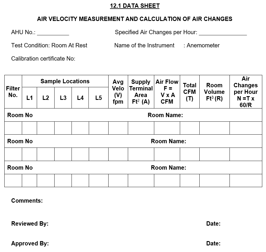
6.1 AIR VELOCITY MEASUREMENTS AND NUMBER OF AIR CHANGES
6.1.1 Objective
To demonstrate that the air system is balanced and capable of delivering air velocities and providing number of air changes as per requirement when calculated as per the respective room volumes.Also calculate the number of air changes considering the air velocities obtained from the terminal grill filters.
6.1.2 Equipment Used: Anemometer
6.1.3 Method Applied
- Ensure that the blowers are switched “ON” prior to the start of the observations.
- Ensure the Calibration status of the Anemometer.
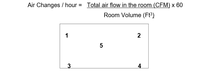
- Measure the air velocity 2 inches below the grill, at 5 locations (Four Corners and center) with the Anemometer and record.
- Calculate the average velocity of the air coming from Supply Grill.
- Calculate the airflow by multiplying the average velocity with the effective filter area.
Air flow= Average Velocity x Face Area of the Air Inlet Grill / Filter
= Ft / Min. X Ft2
= Ft3 / Min. or CFM
Calculate the airflow for all the supply grills in the room and add values to get the total airflow in the room (CFM).
Calculate the number of air changes per hour in the room by using the formula:
6.1.4 Acceptance Criteria
Minimum and maximum velocity and subsequent airflow across the HEPA filter should be within the design specification range to achieve the specified range of Air changes and Differential pressure of the clean room.
The variation among the average velocity across the terminal grill supplying to the same room should not be more than ±20%.
6.1.5 Result Recording
Raw data shall be collected in the data sheet. Measure and record the air velocity at five points of each Supply Grill. Recording shall be done in Validation Report # 1 for respective rooms. Calculate the average velocity and record it in the same Validation Report # 1 average velocity shall be used to calculate the air supply to each room and air change rate. Calculation is given in the same Validation Report # 1. Attach the calibration certificate of anemometer with the report.
6.1.6 Evaluation of result:
The result complying with the specification range of individual velocity of the HEPA filter shall achieve the desired airflow of the room and air change rate.
If velocity is not within the specified limit, damper should be regulated, and if the minimum velocity is not achievable, filter should be changed, irrespective to other test complying with the acceptance criteria.
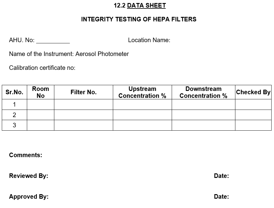
6.2 INTEGRITY TEST OF HEPA FILTERS
6.2.1 Objective
To check the installed HEPA Filter integrity of terminal HEPA filters.
6.2.2 Equipment Used
Cold DOP smoke generator, Aerosol photometer, duly calibrated with national/international traceability certificate.
6.2.3 Method Applied
Filter testing shall be performed by external agency only after operational air velocities have been verified and adjusted wherever necessary.
Position the smoke generator and introduce DOP smoke into the air stream, ahead of the HEPA filters, at the concentration of 20 – 80mg per liter of air at the filter’s designed airflow rating and set the instrument at 100% concentration. Scan the downstream side of the filter with an appropriate photometer probe at a sampling rate of at least 1 ft3 / min. The probe should scan the entire filter face and frame at a position about 1 to 2 inches from the face of the filter. Scanning shall be done at the rate of maximum 2 feet per minute.
6.2.4 Acceptance Criteria
During scanning percentage of DOP penetration shown by photometer should be less than 0.01% through the filter media and should be ‘zero’ through mounting joints.
6.2.5 Result Recording
Record the results in the Validation Report # 2. Record the details of the instruments used, including their calibration status, filter identification number, location, and upstream and downstream concentration of DOP.
Attach the calibration certificate of the photometer with the report.
6.2.6 Evaluation of result
Results complying with the acceptance criteria shall establish the integrity of the HEPA filter suitable for clean area.
If any leakage is observed from the mounting, it has to be rectified through adjustment and application of food-grade silicone sealant.
If leakage is observed from the Filter media more than the acceptable limit, filter shall be replaced with new one and qualified.
Accepted limit for filter leakage
Any leakage greater than 0.01% of the upstream challenge aerosol concentration is considered unacceptable and requires repairs and resetting.
Repair patches on the HEPA Filter should not exceed a maximum of 5% of the total filter, and Maximum width or height of any patch should not exceed 1.5 inches.
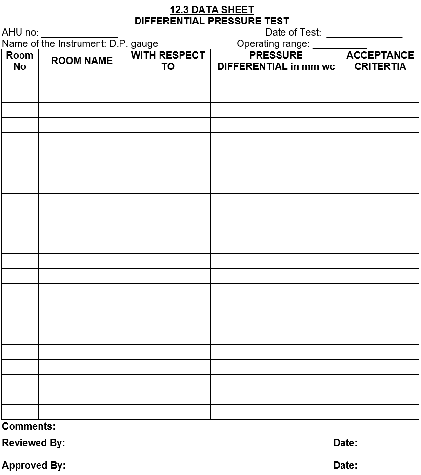
6.3. AIR PRESSURE DIFFERENTIAL TEST
6.3.1 Objective
To demonstrate the capability of the air system to provide pressure gradient among the different rooms.
6.3.2 Equipment Used
Magnehelic gauges
6.3.3 Method Applied
All HVAC systems shall be in continuous operation.
To avoid unexpected changes in air pressure and to establish a baseline, all doors in the facility must be closed, and no man movement is allowed during the observations. Observe the differential pressure through Magnehelic gauge.
Differential pressure of the room shall be recorded once in an hour for 72 hours.
6.3.4 Acceptance Criteria
- Pressure differentials across the two rooms of different class should be more than 1.5 mm WG
- Pressure differentials across the two rooms of same class should be more than 0.5 mm WG
- Pressure differentials should be maintained as indicated in the design conditions under standard operating condition.
6.3.5 Result Recording
Measure and record differential Pressure in the Validation Report # 3.
6.3.6 Evaluation of Results
Results complying with the acceptance criteria and design requirement shall indicate the correct balancing of Air Handling System. In case of failure to meet the specifications, adjustment in the return damper shall be done. Transient drop in differential shall be recorded, and investigation shall be done to find out the reason. Corrective action shall be taken if required.
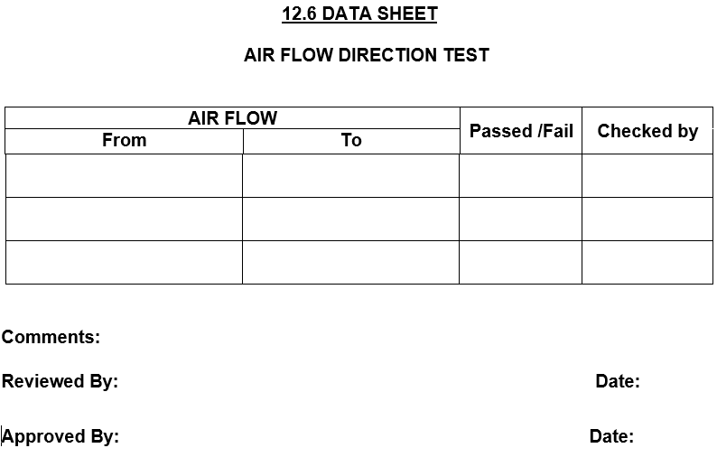
6.4 AIRFLOW PATTERN TEST
6.4.1 Objective
To demonstrate that the air system is balanced so that airflows through out the process area to corridor and the airflow is uniform under terminal grill.
6.4.2 Procedure
Take a glass stick with cotton or sponge tied to it. Dip it in Titanium Tetrachloride solution (TiCl4) and check for airflow direction in the rooms, under terminal grill, return filter or grill, and corridor to process area with the doors of the room both in open and closed condition.
6.4.3 Acceptance Criteria
- Air should flow from the higher-pressure zone to low pressure zone.
- The air should flow towards the return air filter or grill.
6.4.4 Observations and Result Recording
Observe the air flow pattern as per the procedure mentioned above and record in the Validation Report # 4.
6.4.5 Evaluation of Result
Analyzing the airflow pattern, recorded in the test report, it can be concluded that the airflow pattern follows the acceptance criteria.
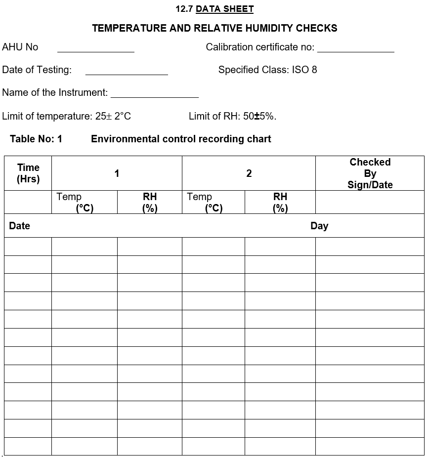
6.5 TEMPERATURES AND RELATIVE HUMIDITY CONTROL TEST
6.5.1 Objective
To demonstrate the ability of the HVAC system to provide temperature and Relative Humidity within the specified range.
6.5.2 Equipment Used: Thermometer & RH sensor
6.5.3 Method Applied:
Air conditioning system shall be in continuous operation for at least 24 hours prior to performing these tests. All lights in the critical area and controlled clean area shall be ON during the testing as well as during the 24 hours pre-conditioning period.
Place instruments near the return grill; keep them for a minute for stabilization and record the observation.
6.5.4 Acceptance Criteria
The system shall be considered acceptable if the temperature and RH monitored during 72 hours at all locations falls within the specified temperature range.
The temperature of the area should be 25 ±2OC and the Humidity should be 50±5%.
6.5.5 Results
Measure and record temperature and RH at the locations specified for every room in the drawing attached as Attachment. Record the observations in the Validation Report# 5 at an interval of 60 minutes for a period of 72 hours in each location, which includes both static and dynamic conditions.
At rest condition: Room with lights on and no machine in operation. Only operator will be present in the area for recording.
In operation condition: Rooms with lights on with normal man movement.
6.5.6 Evaluation of Result
On the basis of the observations recorded in the test reports, it can be concluded that the HVAC system is capable of consistently maintaining the required temperature and relative humidity in the controlled areas.
6.6 NON–VIABLE AIR BORNE PARTICLE COUNT TEST
6.6.1 Objective
To establish that in critical work locations within critical and non-critical areas meet the requirement for cleanliness class as per ISO 14644-1standard.
6.6.2 Equipment Used
Airborne particulate counter, duly calibrated with national/international traceability.
6.6.3 Method Applied
Air conditioning system shall be in continuous operation for at least 24 hours prior to performing these tests. Particulate count for all pre decided location (layout attached) in each location take 3 readings at the working height, shall be taken. Number of sampling locations will be decided as per the ISO 14644-1.
Number of sampling locations: √A
Where A is area of cubicle in sq meters
FORMULA
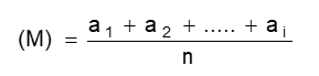
Calculate the reading as per the formula mentioned below:
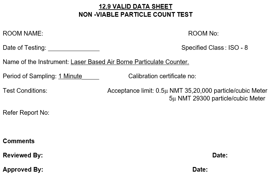
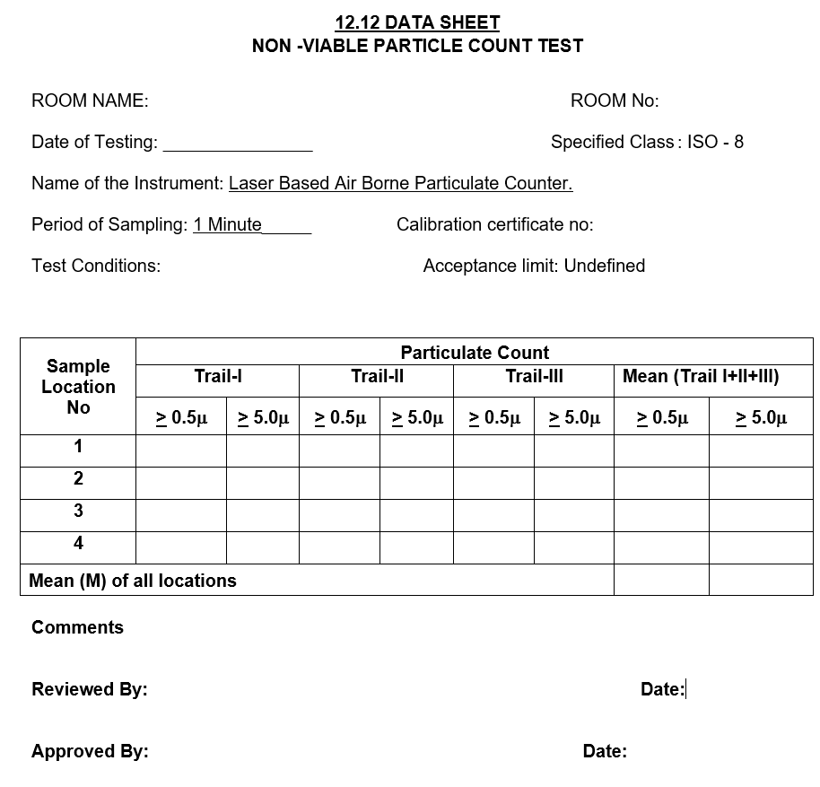
6.6.4 Acceptance Criteria
The clean room or clean zone shall meet the acceptance criteria for an airborne particulate cleanliness if:
01. The average of the particulate count measured at each location falls at or below the class limit
The particle count of the area should not be more than 3520000 (³ 0.5 m size) and29300 (³ 5.0m size) per cubic meter “at rest condition”.
The particle count of the area is Undefined “in operation condition”.
6.6.5 Result Recording
Data shall be collected in the data sheet. Measure and record the particulate count at various locations as per attached layout. Recording shall be done in Validation Report # 6. Calculate the average count for each location/zone and record it in the same data sheet.
Attach the calibration certificate of Particle Counter with the report.
6.6.6 Evaluation of result:
The calculated count should be as per the specified class range for individual areas.
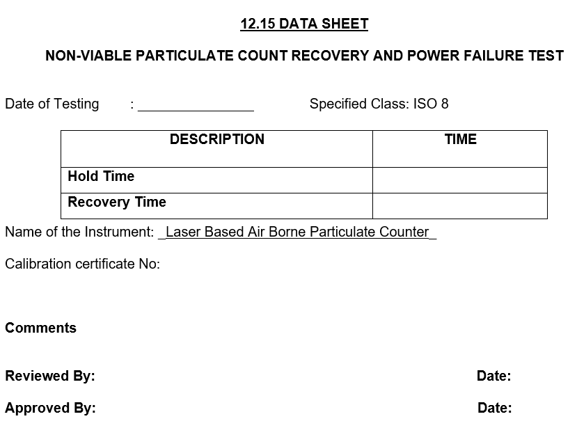
6.7 RECOVERY TEST
6.7.1 Purpose
To Determine Air handling unit recovery of particles to its original condition.
6.7.2 Equipment Used
Airborne particulate counter, duly calibrated with national/international traceability.
6.7.3 Method Applied
Switch off the Air handling unit and start the particle count check until the particles shall reach the more than specified class. Start the Air handling unit, take the reading until reaches rest condition position, and record the time taken to reach its rest condition.
6.7.4 Acceptance Criteria
The clean room or clean zone shall meet the acceptance criteria for recovery time shall not be more than 20 minutes.
6.7.5 Result Recording
Data shall be collected in the data sheet. Measure and record the particulate count at the locations as per attached layout. Recording shall be done in Validation Report # 7.
6.7.6 Evaluation of result:
Record the recovery time of the AHU in the Validation Report #7.
6.8 MICROBIAL MONITORING:
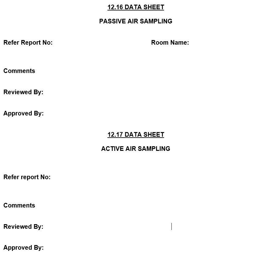
PASSIVE AIR SAMPLING:
6.8.1 Objective:
To determine the viable airborne microbial contamination level in air for the Process rooms.
6.8.2 Procedure
SCDA / SDA plates shall be exposed on the working plane in the area. Plate exposure shall be done under dynamic conditions. Plate shall be exposed for 4 hours. Exposed plates shall be incubated at 20 to 25°C for 72 Hrs, followed by 30 to 35°C for a further 48 Hrs. Plates shall be observed for any microbial growth after 5 days.
In dynamic conditions, normal man movement shall be there.
The Sampling shall be done in three consecutive working days.
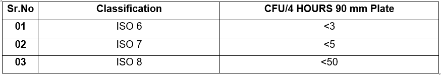
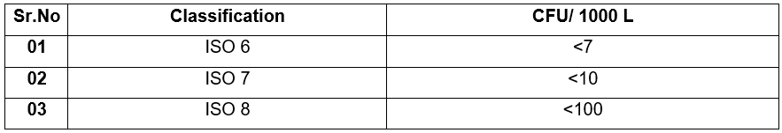
6.8.3 Acceptance Criteria:
ACTIVE AIR SAMPLING:
6.8.4 Procedure
Operate the Air sampler as per the SOP and collect air samples of 1000 L volume at the designated locations as per the sampling plan attached. Sampling shall be carried out in dynamic conditions. After sampling, remove the plate from the sampler aseptically. Label the location number, block, and date on plate. Exposed plates shall be incubated at 20 to 25°C for 72 Hrs, followed by 30 to 35°C for further 48 Hrs.
In dynamic condition, normal man movement shall be there.
The Sampling shall be done in three consecutive working days.
6.8.5 Acceptance Criteria
6.8.6 Evaluation of Result
All microbial results complying with the acceptance criteria will establish the microbial environment suitable for operation. Any microbial found in the sample shall be identified and investigated for the source of contamination, and decision on the HVAC System qualification shall be taken.
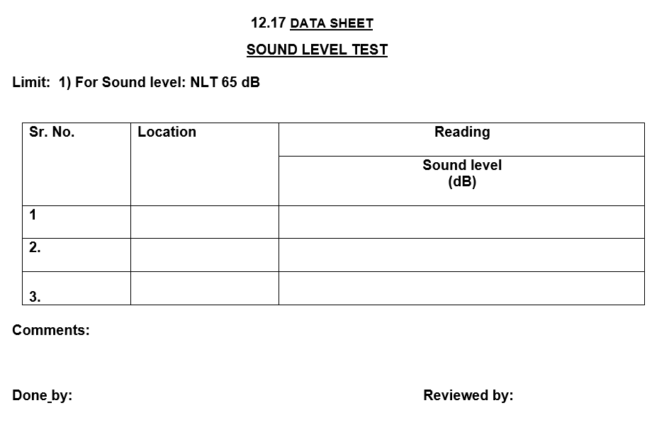
6.9 SOUND LEVEL TEST:
6.9.1Purpose:
To measure the airborne sound pressure levels produced by operating AHU.
6.9.2 Instruments used:
Digital Sound Level Meter
6.9.3 Conditions for testing:
All the noise/sound making system in the proximity of the area shall be switched off.
6.9.4 Testing procedure:
The instrument is to be set for the following values:
i) 65 dB,
ii) Fast response mode.
ii) Keep the probe of the sound level meter at 1 meter from the unit.
iii) Note down the values at the test spots.
6.9.5 Acceptance criteria:
i) The sound level should be less than 65 dB at the working area.
ii) Data sheet for sound level monitoring shall be attached with the protocol
6.10 BLOWER CFM, MOTOR RPM, CHILLED & HOT WATER TEMPERATURE
6.10.1 Purpose: To measure and establish various parameters of the system specified in the functional specification
6.10.2 Tools required: Tachometer and Anemometer.
6.10.3 Test procedure: A minimum of three observations to be made.
Measure the speeds/rpm (wherever mentioned) using a Tachometer.
Measure the air velocities (wherever mentioned) using an Anemometer.
Measure the temperature (wherever mentioned) using a Thermometer.
6.10.4 Acceptance criteria: The observations made should be same as the specified function.
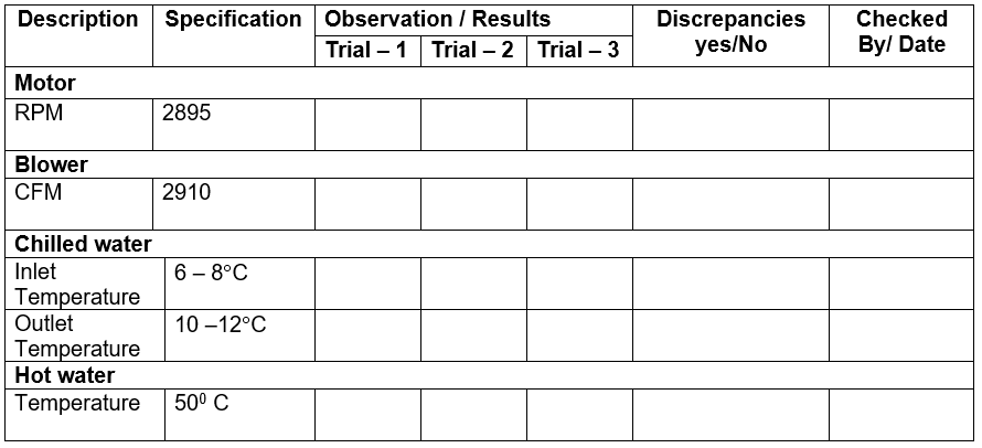
6.10.5 Verification of design parameters:
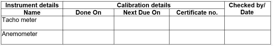
7.0 TEST INSTRUMENT DETAILS:
| Sr. No. | Name of instrument | Identification No. | Make /Model | Calibration valid up to | Checked by |
8.0 DISCREPANCIES AND CORRECTIVE ACTION TAKEN.
Discrepancies:
———————————————————————————————————————————————————————————————————————————————————————————————————————————————————————————————————————————————————————————————————————————————————————————————————————————————————————
———————————————————————————————————————————————————————————————————————————————————————————————————————————————————————————————————————————————————————————————————————————————————————————————————————————————————————
Corrective action taken:
———————————————————————————————————————————————————————————————————————————————————————————————————————————————————————————————————————————————————————————————————————————————————————————————————————————————————————
———————————————————————————————————————————————————————————————————————————————————————————————————————————————————————————————————————————————————————————————————————————————————————————————————————————————————————
Reviewed by:
Date:
9.0 Annexure (s):
| Sr.No. | Annexure No. | Title of Annexure |
10.0 ABBREVIATIONS SHEET:
| SR. NO | ABBREVIATION | DESCRIPTION. |
| 1. | PQ | Performance qualification. |
| 2. | AHU | Air Handling Unit |
| 3. | CFM | Cubic feet per minute |
| 4. | NLT | Not Less than |
| 5. | CFU | Colony forming units. |
| 6. | NMT | Not more than |
| 7. | RH | Relative humidity. |
| 8. | FPM | Feet per minute |
11.0 SUMMARY AND CONCLUSION
Summary:
———————————————————————————————————————————————————————————————————————————————————————————————————————————————————————————————————————————————————————————————————————————————————————————————————————————————————————
—————————————————————————————————————————————————————————————————————————————————————————————————————————————————————————————————
——————————————————————————————————————————————————————————————————————————————————————
Conclusion:
———————————————————————————————————————————————————————————————————————————————————————————————————————————————————————————————————————————————————————————————————————————————————————————————————————————————————————————————————————————————————————————-
—————————————————————————————————————————————————————————————————————————————————————————————————————————————————————————————————
——————————————————————————————————————————————————————————————————————————————————————
12.0 FINAL REPORT APPROVAL:
It has been verified that all tests required by this protocol are completed, reconciled, and attached to this protocol or included in the qualification summary report. Verified that all amendments and discrepancies are documented, approved, and attached to this protocol.
Signature in the block below indicates that all items in this performance qualification report of air handling unit have been reviewed and found to be acceptable and that all variations or discrepancies have been satisfactorily resolved and the system is qualified for its routine use.
| NAME | DESIGNATION | DEPARTMENT | SIGNATURE | DATE |
| PROJECTS/ ENGINEERING | ||||
| PRODUCTION | ||||
| QUALITY ASSURANCE |

Naresh Bhakar is the Founder and Author at Pharmaguddu.com, bringing his extensive expertise in the field of pharmaceuticals to readers worldwide. He has experience in Pharma manufacturing and has worked with top Pharmaceuticals. He has rich knowledge and provides valuable insights and data through his articles and content on Pharmaguddu.com. For further inquiries or collaborations, please don’t hesitate to reach out via email at [email protected].