GMP & Pharmaceutical Manufacturing Expert
✓ Reviewed by: Pankaj Sharma - Quality Control Specialist
Reviewed for Quality Control accuracy, laboratory practices, analytical methods, and technical relevance
📅 Last Updated: May 13, 2026
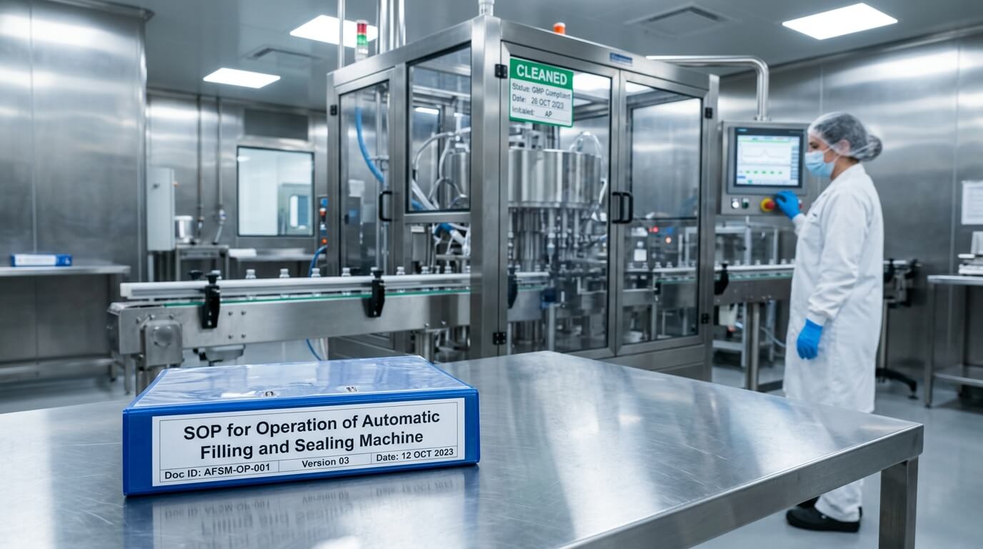
1.0 OBJECTIVE: To lay down the procedure for operation of Automatic Filling and Sealing Machine.
2.0 SCOPE: This procedure is applicable for operation of Automatic Filling and Sealing Machine in liquid department.
3.0 RESPONSIBILITY:
3.1 Operator / Production Staff
To operate the equipment/machine as per approved SOP.
To clean the equipment after use and keep the area clean.
3.2 Production Officer/Supervisor
To ensure the procedure is properly followed by production personnel.
To inspect equipment for cleanliness and working condition.
3.3 Manager/Head of Department (HOD)
To ensure implementation & compliance of this SOP.
3.4 Department of Quality Assurance (QA)
To approve and review the SOP and any changes to it.

4.0 PROCEDURE:
4.1 FILLING MACHINE:
4.1.1 The machine consists of the following parts:
- Slat conveyor belt.
- Synchronised bottle feeder.
- Bottle actuating device.
- Bottle starplate for feeding and discharging.
- Four numbers of filling heads and four numbers of sealing heads.
- Cap feeder with chute.
- “No bottle, no fill” liquid level sensor.
- Variable speed pulley drive arrangement.
4.1.2 After line clearance from Q. A. put “UNDER PROCESS” label on the machine as per Annexure – II.
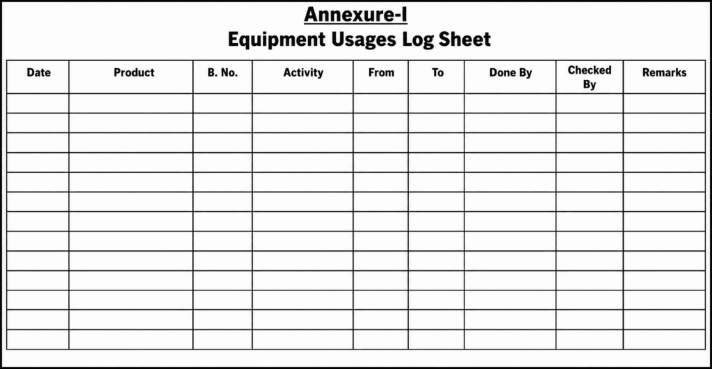
4.1.3 Enter start time of the batch in Equipment Usages Log Sheet as per Annexure – I.
4.2 Keep the machine selector switch in the “INCH” position, then switch it to the “MAN” (Manual) position for machine setting.
4.3 Keep the hopper filling switch in the “MAN” (Manual) position to start liquid filling into the tank.
4.4 Adjust the position of “Star Plate” to match with the position and height of filling Nozzle.
4.5 SET THE “HOPPER LEVEL CONTROLLER” BY ADJUSTING THE “FILLING DELAY” AND “ALARM DELAY” FOR LIQUID /SUSPENSION:
4.5.1 For Liquid Syrup, keep “Filling Delay” Switch on 5 and “Alarm Delay” on 20.
4.5.2 For Suspension, keep “Filling Delay” Switch on 2 and “Alarm Delay” on 20.
4.6 Adjust the volume by using Micro screw provided near to the cam track.
4.6.1 Turn the screw by spanner in clockwise direction to increase the volume.
4.6.2 Turn the screw by spanner in anti-clockwise direction to decrease the volume.
4.7 Volume of all syringes can be adjusted simultaneously with the help of the microscrew.
4.8 Start the pump, which is operated by proximity switch provided on top cover of liquid storage tank. As soon as the tank is filled up to a certain level, the liquid transfer pump will stop automatically by sensing the liquid level in the tank, and if the level is low, it will start automatically.
4.9 After the tank gets full, put the Hopper filling switch on “AUTO” position.
4.10 Bring out the syringe assembly from the front side of the machine where the top cam track is cut.
4.11 Remove the top cap of barrel and pull out the piston from its barrel.
4.12 Remove the syringe barrel by unscrewing the 4 fixing bolts.
4.13 Set the bottle height by pressing the switches provided on the back side of the machine.
4.14 SEALING MACHINE:
4.14.1 The sealing unit consists of the following parts:
- Center star plate and bottle guide.
- Sealing head assembly.
- Bottle discharge star plate and bottle guide.
- Sealing head assembly.
- Sealing head height adjusting assembly.
- Cap feeder with chute.
4.15 Adjust the sealing head height by loosening the bolt on top drum.
4.16 Take the sealing head at a position higher than selected bottle height.
4.17 Keep the unsealed loose cap on the bottle base.
4.18 Decrease the sealing head height till the bottle slides slightly by using green push button, then retighten the allen bolt carefully.
4.19 After adjusting the height of the sealing head, set the sealing head individually one by one.
4.20 Loosen the allen bolt of sealing rollers holding block and adjust the roller to touch the bottom groove of the cap, and for the threading, touch the corner edge of threading rollers to the cap neck groove of the cap. Retighten allen bolt by holding block carefully.
4.21 Set the hopper by adjusting the feeding of the cap orientation by adjusting 4 adjusting bolts.
4.22 Set the hopper properly and retighten the lock nut.
4.23 Enter ending time of the batch in Equipment Usages Log Sheet as per Annexure – I.
4.24 Affix “TO BE CLEANED” label on the machine as per Annexure – II.
Related SOP: SOP on Procedure for Making Entries in Equipment Usage Log Book
4.25 NOTE:
4.25.1 Ensure adequate oil level by reduction gearbox.
4.25.2 Ensure air pressure in the unit is not less than 50 psi.
4.25.3 Lubricate daily all moving parts with food-grade oil when product comes in contact and grease for closed parts.
4.25.4 Never start the machine in reverse direction.
4.25.5 Do not drop oil on torque limitation clutch or on the vary belt.
4.25.6 The speed of machine can be varied from 2400 to 4800 bottles per hour.
4.25.7 No bottle, no filling arrangement is provided to avoid spillage of liquid.
5.0 ANNEXURE (S):
ANNEXURE-I: Equipment Usages Log Sheet
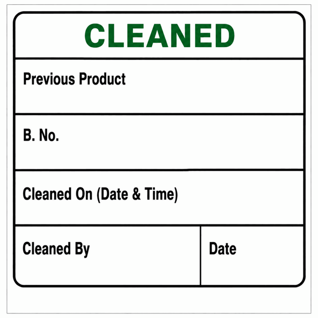
ANNEXURE-II: Cleaned label
6.0 ABBREVIATION (S):
SOP: Standard Operating Procedure.

Naresh Bhakar is the Founder and Author at Pharmaguddu.com, bringing his extensive expertise in the field of pharmaceuticals to readers worldwide. He has experience in Pharma manufacturing and has worked with top Pharmaceuticals. He has rich knowledge and provides valuable insights and data through his articles and content on Pharmaguddu.com. For further inquiries or collaborations, please don’t hesitate to reach out via email at [email protected].