GMP & Pharmaceutical Manufacturing Expert
✓ Reviewed by: Pankaj Sharma - Quality Control Specialist
Reviewed for Quality Control accuracy, laboratory practices, analytical methods, and technical relevance
📅 Last Updated: June 14, 2026
Quick Answer
The Effluent Treatment Plant (ETP) is a wastewater treatment plant installed at the pharmaceutical manufacturing premises which is used to treat the effluents generated during the manufacturing processes before these effluents are discharged to the municipal sewer, water body or reused in the manufacturing premises. Ordinary sewage systems are not suitable for the processing of pharmaceutical effluent often contaminated with residual active pharmaceutical ingredients (APIs), solvents, high COD/BOD load and varying pH. The ETP comprises physical, chemical and biological treatment steps (screening, equalization, neutralization, coagulation-flocculation, biological degradation and tertiary polishing treatment) to reduce pollutant concentrations to within limits set by pollution control boards.
Key Takeaways:
- An ETP is used to treat pharmaceutical wastewater to a standard that complies with the local and national pollution control authorities discharge norms.
- Pharmaceutical effluent is more complicated than municipal waste due to the presence of API residues, solvents, antibiotics and disinfectant by-products.
- There are three stages of treatment: primary (physical), secondary (biological) and tertiary (polishing/advanced).
- The core of most pharmaceutical ETPs is biological treatment, either activated sludge, MBBR or SBR.
- Biological treatment (either activated sludge, MBBR or SBR) is the backbone of most pharmaceutical ETPs as it removes dissolved organic load (BOD/COD).
- A concern that is frequently recorded in environmental and GMP inspections is poor ETP performance (particularly where discharges to watercourses are exceeded).
- In most jurisdictions sludge produces by the ETP is classified as hazardous waste and deals with its handling, storage and disposal according to local EHS regulations.
- In many parts of the world, bulk drug (API) manufacturing units are being increasingly subjected to Zero Liquid Discharge (ZLD) requirements.
- Daily pH, flow and basic parameter monitoring helps to identify deviations in the upstream process that could become compliance challenges (Check full detail below).
What Is an Effluent Treatment Plant?
An Effluent Treatment Plant is a wastewater treatment plant used for collecting, treating and conditioning of the liquid effluent produced by the pharmaceutical manufacturing process before it is released from the manufacturing facility. This encompasses wastewater generated as a result of API synthesis, formulation wash, equipment wash, blowdowns from utilities, and lab activities.
Effluent is not a single stream in a pharmaceutical plant; it is a composite of streams, which have very different characteristics. Effluents that could be generated from solvent recovery operations include high COD and low pH effluents, and effluents from formulation area cleaning include surfactants and trace amounts of API. The ETP should treat this mixed and inconsistent quality stream and reduce it to a uniform quality stream that can be discharged.
An ETP is designed to accept a high volume of pollutants, most of which are generated in an industrial manner (e.g. chemical, paint shop, washdown) and may even be dangerous to the biological treatment process if not properly controlled, unlike the main industrial effluent generated by a Sewage Treatment Plant (STP) which is of the domestic type (i.e. toilets, canteen, washrooms).
ETP Definition:
An Effluent Treatment Plant is an engineered facility of unit operations (physical, chemical and biological) which are designed to reduce the level of pollutants (BOD, COD, TSS, oil and grease, and specific chemical contaminants) to within statutory limits before releasing the treated effluent into the environment or for safe re-use.
What are the Principles of an ETP?
An ETP operates by filtering out contaminants in a series of stages, each one removing more pollutants: first the big solids and oils, then dissolved chemicals through pH adjustment and by chemical dosing, then dissolved organic matter by means of the biological digestion of organic matter by microorganisms, and finally any trace remaining by polishing processes such as filtration or activated carbon.
Each stage aims to tackle a particular type of pollutant. Skipping a stage (e.g. highly acidic effluent straight to the biological tank) will adversely affect the biological treatment process as the organisms that degrade organic matter are not tolerant to sudden pH changes.
Working Principle:
Inflow: Waste combination from production processes, blowdowns from the utilities, equipment washing, and floor drains are gathered in a separate effluent drainage system and stored in a collection/equalization tank.
ETP Process flow:
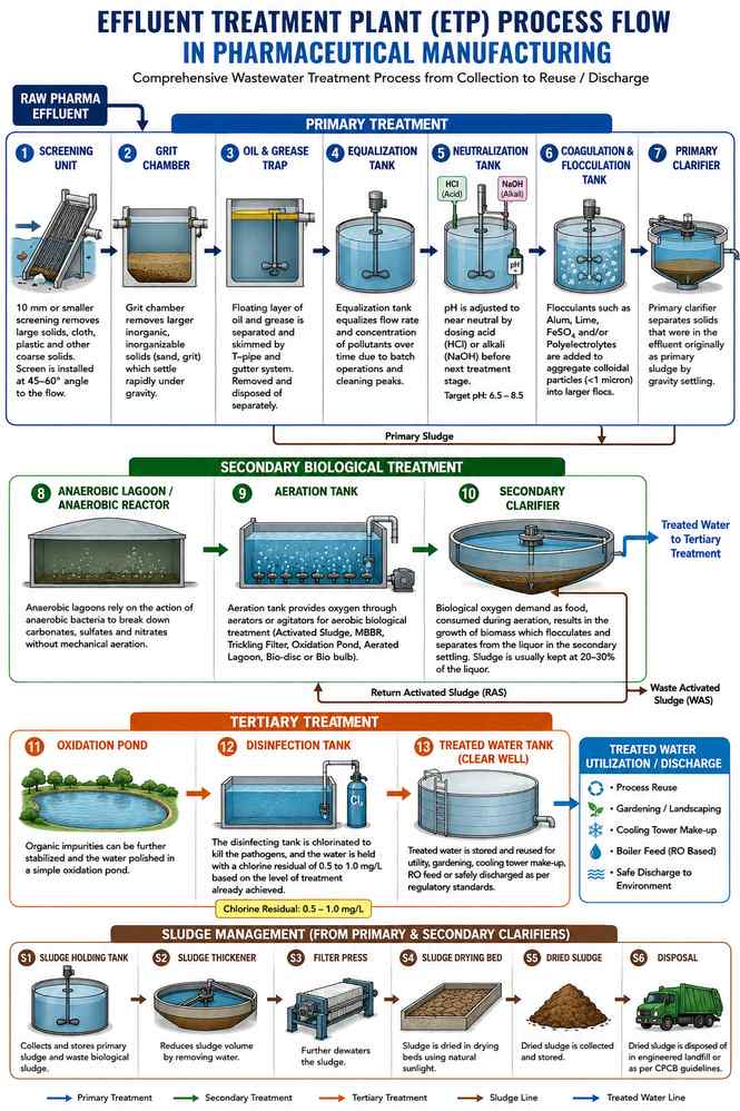
- The 10 mm or smaller screening is used to remove large solids, cloth, plastic and other coarse solids from the flow, usually at an angle of 45 to 60 degrees to the vertical and at right angles to the flow direction.
- Grit chamber removes larger inorganic, inorganizable solids (sand, grit) which settle rapidly under gravity.
- Floating layer of oil and grease from the lubrication system, boilers, cooling towers, and boiler blowdown is separated and skimmed from the water by a T-pipe and gutter system, which is removed and disposed of separately.
- Equalization tanks are used to equalize flow rates and concentrations of pollutants over time, as the effluent from pharmaceutical production is not always uniform, but peaks during batch cleaning operations, etc.
- The pH of the water is adjusted to a near neutral pH by dosing with acid (e.g., HCl) or alkali (e.g., NaOH); this is necessary before the water is taken to the next treatment stage.
- Primary clarifier separates solids that were in the effluent originally as primary sludge by gravity settling.
- The term flocculation is used to refer to the use of flocculants, which are substances such as alum, lime, ferrous sulphate (FeSO4) and/or poly-electrolytes, that facilitate the aggregation of the smaller particles, below 1 micron, which are colloids and can settle out of the water.
- Anaerobic lagoons rely on the action of anaerobic bacteria to break down carbonates, sulfates and nitrates without mechanical aeration.
- Aeration tank provides oxygen through aerators or agitators for aerobic biological treatment such as activated sludge, trickling filter, oxidation pond, aerated lagoon, bio-disc or bio bulb.
- The biological oxygen demand as food, consumed during the aeration process, results in the growth of biomass which flocculates and separates from the liquor in the secondary settling where sludge is usually kept at 20-30% of the liquor.
- Sludge drying bed to dry the sludge settled in the clarifiers for using it as landfill.
- Organic impurities can be further stabilized and the water polished in a simple oxidation pond.
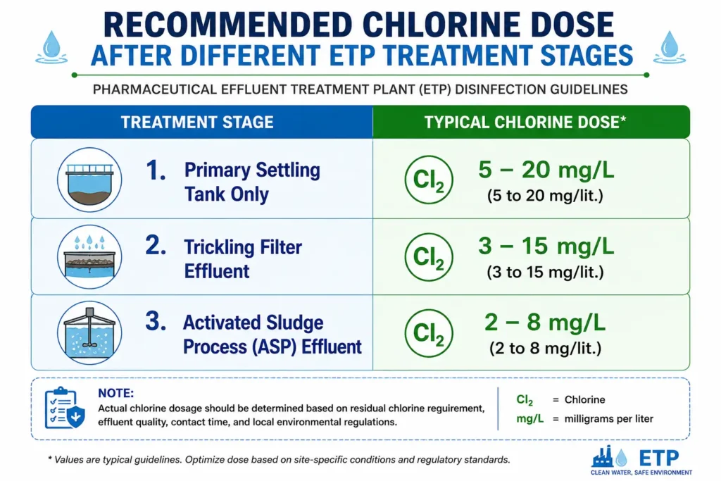
- The disinfecting tank is chlorinated to kill the pathogens, and the water is held with a chlorine residual of 0.5 to 1.0 mg/L based on the level of treatment already achieved.
Output: Discharge water that complies with discharge standards, discharged to municipal sewer, to surface water body (with permission), or sent to a third party for reuse (after QC testing and discharge), for cooling tower makeup, or for treatment towards the Zero Liquid Discharge.
| Parameter | Range (Pharmaceutical ETP) |
|---|---|
| Inlet COD | 1,000–10,000 mg/L, with API manufacturing units sometimes exceeding 10,000 mg/L depending on the process. |
| Inlet BOD | 300–3,500 mg/L |
| Outlet COD (General Discharge Standard) | Below 250 mg/L for discharge into inland surface waters, sewers, or land for irrigation. |
| Outlet BOD (General Discharge Standard) | Below 30 mg/L for discharge into inland surface waters, sewers, or land for irrigation. |
| pH Range for Biological Treatment | 6.5–8.5 |
| Dissolved Oxygen in Aeration Tank | 2–4 mg/L |
| MLSS in Aeration Tank | 2,000–4,000 mg/L |
| Hydraulic Retention Time (Equalization) | 6–24 hours, depending on flow variability. |
| Sludge Age (Mean Cell Residence Time) | 5–15 days, depending on process design. |
Main Components of ETP:
Screen:
Goal: To filter out large solids, cloth, plastic and other coarse debris from incoming wastewater.
Function: A physical barrier, normally between 10 to 15 mm in size, installed at an angle of 45 to 60 degrees to the vertical and at an angle 90 degrees to flow to be able to capture debris as the effluent passes through.
Operating Role: First line of defense for downstream pumps, pipes and tanks from coarse material clogging.
Common issues: Excessive debris causing screen blinding, wrong installation angle that will reduce the capture efficiency, and lack of manpower for timely clean-up of the screens causing overflow.
Grit Chamber:
Aim: To filter out heavier, inert inorganic solids like sand and grit before they get to downstream tanks.
Action: It utilizes the properties of rapid settling of grit (inorganic, inert, and heavier than organic solids) to separate it from flow under gravity.
Function: To prevent abrasive wear on pumps, pipes and equipment downstream by keeping grit from building up.
Common Issues: Less than regular cleaning of grit, which causes the buildup of grit and leads to a decrease in the effective volume of the chamber; and grit carry over to downstream tanks when the flow velocity up through the chamber is too high.
Oil and Grease Trap:
Applications: To remove floating oil and grease from wastewater streams from lubrication systems, boilers, cooling towers or boiler blowdown.
Action: Discards the floating layer of oil and grease from the flow with a t-pipe/gutter system which is removed from the product stream and diverted to a waste drum for separate collection and treatment.
Function: To prevent oil and grease from coating the biomass and interfering with oxygen transfer in biological treatment stages, if it is not removed early.
Common Issues: Skimming was not done regularly resulting in oil/grease waste being carried over to downstream tanks and failure to dispose of the collected oil/grease waste properly.
Collection and Equalization Tank:
The purpose is to receive the sum of all the effluent streams from the plant and buffer fluctuations in flow and load.
Purpose: to provide mixing of various waste streams resulting in a more homogenous input to the downstream treatment process.
Role: Usually have mixers or aeration systems to keep solids at a level that prevents settling and the generation of odors, and are sized to meet peak flows and hydraulic retention time requirements.
Common Issues: If the tank is undersized, it can cause hydraulic overload during peak production; if it’s not properly mixed, solids settle and cause odors.
Neutralization Tank:
Purpose: To adjust the pH of effluent to a desirable level for subsequent chemical and biological processing.
Function: adding acid (typically sulfuric or hydrochloric) or alkali (typically lime, caustic soda) based on the measured pH on-line or periodically.
Operating role: Many ETP upsets are due to incomplete or inconsistent neutralization — often the first line of defense. Typical chemical requirements include an addition of about 1.0 mg/liter CaCO3, 0.56 mg/liter CaO, 0.74 mg/liter Ca(OH)2 or 0.8 mg/liter NaOH to neutralize 1 mg/liter of acidity. The typical requirements for neutralisation of 1mg/liter of alkalinity are about 0.98mg/liter of sulphuric acid, 0.72mg/liter of hydrochloric acid, 1.26mg/liter of nitric acid and 0.62mg/liter of carbonic acid. The dose should always be verified by jar testing and online pH feedback, due to the variability between effluent characteristics of streams.
Common issues: pH probe drift or fouling, dosing pump failures and rapid pH changes caused by batch dumps of process waste of either an acidic or alkaline nature.
Coagulation-Flocculation Unit:
Purpose: Chemical Precipitation is used for the purpose of removing suspended solids, colloidal particles and some dissolved organics by chemical precipitation.
Function: Coagulants destabilize suspended particles and flocculants aid the formation of larger flocs that will settle.
Operation: Dosing rates must be periodically checked against jar tests due to effluent variability with production schedules.
Common Issues: Over- or under-dosing, poor floc formation due to temperature or pH issues, and excessive sludge generation when dosing is not optimized.
Primary Clarifier / Settling Tank:
Purpose: Removes the settleable solids (primary sludge) from the liquid stream following chemical treatment.
Use: Gravity settling separates flocculated solids from the liquid, which will be clarified.
Maintenance requirement: Scrapers for sludge must be operated and sludge removed from the settling pool in time to ensure settling efficiency.
Common Issues: Reduction of settling time due to short circuiting of flow, failure of scraper mechanism and sludge bulking.
Biological Treatment Unit (Activated Sludge / MBBR / SBR):
Description: Dissolved organic load (BOD/COD) reduction using microorganisms.
Function: aerobic bacteria break down organic pollutants that are used as food, dissolved oxygen provided by aerators or diffusers.
Operation: The Performance here is at the center of ETP — Discharge BOD/COD limits depend upon the performance here. Very critical on dissolved oxygen, food-to-microorganism (F/M) ratio and sludge age.
Common Issues: Solvent or antibiotic peaks causing toxic shock, causing biomass loss; low dissolved oxygen; and foaming, or settling poorly (bulking sludge).
Anaerobic Lagoon:
It will treat the waste biologically using anaerobic bacteria without mechanical aeration. The function is determined as follows: aerobic bacteria break down carbonates, sulfates and nitrates in the presence of free oxygen, but facultative bacteria may break down carbonates, sulfates and nitrates with or without free oxygen. Often employed as an initial or subsequent biological stage, especially when embankment type tanks (lagoons) can be used and aeration is restricted.
Common Issues: Anaerobic by-product odors (H2S), insufficient retention time, and control of the process compared to mechanically aerated systems.
Secondary Clarifier:
Aim: Removes treated biomass (secondary sludge) from the treated water stream.
Function: It is used to give biological floc settling time and to have the treated water overflow for additional polishing.
Return Activated Sludge: Part of settled sludge is re-introduced in the biological tank to keep the biomass concentration high, the rest is wasted to sludge handling.
Common Issues: Sludge carry over to effluent because of poor settling, hydraulic surge or too long a sludge age.
Tertiary Treatment Unit (Filtration / Activated Carbon / Membrane):
Aim: Provide a polished water that meets the requirements of the intended use.
Function: Fine suspended particles are removed by sand or multimedia filters; residual organics and compounds that cause color are adsorbed by the activated carbon filters; membrane systems (UF/RO) may be used if there is a reuse or ZLD objective.
Operating Role: Last quality check prior to discharge/reuse.
Common issues: Filter media clogging, carbon exhaustion for regeneration/replacement and membrane fouling.
Sludge Handling System:
Purpose: Removes water and conditions sludge from primary and secondary treatment facilities for safe disposal.
Function: Usually dewater the sludge using thickeners, centrifuges, filter presses or drying beds to lower moisture content and sludge volume.
Reduces waste that needs to be disposed of as hazardous waste thereby reducing disposal costs.
Common Issues: High disposal volumes due to inadequate dewatering, equipment downtime resulting in sludge backlog and odor problems during storage.
Oxidation Pond:
Application: To be used as a low energy system to further stabilize organic impurities in partially treated effluent.
Purpose: To enable natural biological and physical processes to continue to purify the water for a longer time period in an open pond system.
Operating Role: normally as a polishing stage following primary or secondary treatment, especially if land is available.
Common issues: Unappealing appearance and oxygen imbalance from algae growth, odor when overloaded and less effective in colder water where biological activity is lower.
Chlorination Tank:
Purpose: To disinfect the treated water before discharging or reuse to eliminate the pathogens.
Function: Chlorine is added to the treated water stream, and it also reacts with other chemicals, like ammonia, iron, manganese, sulfide and odor/colour-causing chemicals, which leads to a general process of water purification.
Operating Role: The dose applied will depend on the amount of treatment given upstream; there should be some chlorine residual of 0.5 – 1.0 mg/l.
Common Issues: Excess chlorine residual (residual above target range), inadequate pathogen control (under-dosing) and changes in chlorine demand (when upstream treatment performance changes).
Online Monitoring System:
Purpose: Monitors selected parameters, pH, flow and in some cases COD/TOC at both the inlet and outlet.
Function: Operates to deliver real-time information to the operators and, in certain jurisdictions, to pollution control authorities.
Conditions: When an upset condition is detected before it becomes a non-compliant discharge.
Common Issues: Sensor calibration drift, fouling of probes and connectivity problems with regulatory reporting systems.
Gardening:
Now is the time to do some gardening and reuse Point activities.
Goal: To offer a beneficial use of treated water that complies with reuse standards.
Purpose: Final QC treated effluent is not discharged but used for on-site gardening/landscaping.
Function: Lowers the amount of water discharged and helps meet the water conservation objectives on the site.
Common Issues: Gardening with treated water without QC release or inconsistent QC water quality if upstream treatment performance is variable.
Applications of Effluent Treatment Plants:
- Laboratory-based pharmaceutical formulation manufacturing plants (tablets, capsules, liquids, injectables)
- Active Pharmaceutical Ingredient (API) / bulk drug manufacturing plants
- Biotech/biologics manufacturing facilities
- On-site research laboratories and pilot production units for pharmaceutical products
- Contract manufacturing organizations (CMOs/CDMOs)
- Veterinary pharmaceutical manufacturing units
Benefits of ETP:
- Enables legal and continuous wastewater discharge, avoiding production shutdowns due to environmental non-compliance
- Eliminates additives in the environment, solvents and other chemicals used in the process.
- Enhances water efficiency and supports water reuse programs, reducing fresh water use and operating costs in the long run
- Provides assistance in maintaining a good relationship with local pollution control officials and local communities
- Reflects corporate environmental responsibility, which is becoming key for customer audits and ESG reporting
- Decreases the likelihood of penalties, closure notices or litigation for environmental non-compliance
Limitations of ETP:
- High capital investment for construction, equipment and instrumentation
- Chemicals, energy (in particular aeration blowers) and sludge disposal expenditures are significant on going expenses
- Needs trained and committed staff to operate and monitor daily
- Solvents, antibiotics or pH changes and other shock loads may cause damage to biological systems which may take days to weeks to recover.
- Requires space, especially if adequate retention time is available
- In most areas, sludge is considered hazardous waste, and disposal costs and regulations are increased.
Key Operating Parameters:
pH:
pH Should be kept between 6.5 – 8.5 for biological treatment; values outside this range will cause strain and/or death to the biomass.
BOD:
It Measures biodegradable organic load, monitored at both inlet and outlet to demonstrate treatment efficiency.
COD (Chemical Oxygen Demand):
It measures the total amount of oxidizable matter, both biodegradable and non-biodegradable, such as solvents and complex molecules found in pharmaceutical effluents that give them a high COD-to-BOD ratio.
Total Suspended Solids (TSS):
Impacts clarifier operation and effluent regulations.
Dissolved Oxygen (DO):
Important in aerobic biological treatment; usually kept at 2-4 mg/L in treatment tank.
MLSS (Mixed Liquor Suspended Solids):
Checked to ensure that the biomass concentration in the biological reactor is adequate to enable the treatment and is not so high that settling may be an issue.
Food to Microorganism Ratio (F/M Ratio):
It is a ratio of the organic load to the available biomass, if this ratio is not balanced, it can cause poor treatment or bulking sludge.
Hydraulic Retention Time (HRT):
length of time the effluent remains in each tank – less HRT means less treatment efficiency.
Sludge Volume Index (SVI):
Reflects the settling properties of sludge solids in the clarifier; high values of SVI indicate bulking.
Flow rate:
The flow rate is important as it can vary, particularly if it is a batch dump, which will impact on the size of the equalization tank and downstream stability.
Industry Standards and Regulatory Requirements:
Pharmaceutical facilities face a lot of local and national environmental regulations, and the design and operation of ETPs is based on these regulations, although ETPs are also subject to GMP standards in general site compliance culture. These include national pollution control board consent conditions (discharge limits for BOD, COD, TSS, pH, and specific discharge limits for hazardous substances such as heavy metals or specific solvents), environmental clearance conditions granted for the site, hazardous waste management rules for handling and storage of sludge and land disposal, and occupational safety rules such as confined space entry and chemical handling rules as relevant to ETP operations.
Pharmaceutical residues in the environment are gaining traction for API manufacturing, and the industry and regulators are increasingly referring to environmental risk assessments and targets for discharge of specific APIs, especially antibiotics, within the context of wider antimicrobial resistance (AMR) projects. Pharmaceutical sites, as well as other sites, are often implementing ISO 14001 (Environmental Management Systems), which also has ETP performance as one of its operational controls.
Check current limits and requirements with actual facility consent to operate and local regulations (which can differ markedly between countries, states and even individual receiving water bodies).
Common Problems and Troubleshooting:
High COD/BOD at Outlet:
The discharge of COD/BOD from outlets is exceeding the discharge limits.
Possible Causes:
- Excessive biological loading of the treatment plant (COD/BOD)
- Inadequate dissolved oxygen in aeration tank
- Solvent or antibiotic pollution of biomass
- Flow surges, which mean inadequate hydraulic retention time.
Corrective Actions:
- Update and fine-tune equalization tank action to reduce load spikes
- Check and enhance aeration capacity (blower operation, diffuser condition)
- Find and manage the origin of toxic emission (by properly segregating the origin)
- temporary flow reductions or bioaugmentation (supply of extra biomass)
Excessive Foaming in Aeration Tank:
Possible Causes:
- The presence of detergents or soaps, arising from cleaning activities.
- Too short or long sludge age (too young or too old sludge can result in frothing)
- Presence of filamentous bacteria (Nocardia-type foam)
- Low F/M ratio (filamentous growth)
Corrective Actions:
- Optimize usage of cleaning chemicals and discharge points to minimize the amount of surfactant discharged to the environment
- Increase or decrease sludge wasting rate to restore sludge age within target range
Use anti-foam agents as a temporary solution, until cause(s) is identified & addressed - Check and control DO and F/M ratio to prevent filamentous growth
Sludge Bulking Problems:
Possible Causes:
- Low oxygen (DO) levels or low feed to biomass (F/M) ratio, which can result in filamentous bacteria overgrowth
There are two possibilities for nutrient deficiency in biological tank: Nitrogen deficiency or Phosphorus deficiency. - pH excursions that impact microbial population balance
- Overloading the system, which causes the settling time to be reduced.
Corrective Actions:
- aerate the tank to higher levels of dissolved oxygen.
Monitor and adjust nutrient doses (BOD:N:P ratio typically around 100:5:1) - Check and adjust pH in the last step, neutralization
Limiting flow temporarily, or otherwise equalizing it, so as to minimize hydraulic surges.
Sudden pH Change:
Possible Causes:
- Some process waste is discharged without being pre-neutralized, resulting in high pH levels.
- Failure of dosing pump in the neutralization tank
- Fouling or drift of pH sensor
- Bad equalization tank mixing, resulting in stratification
Corrective Actions:
- Source pre neutralisation for known high/low pH streams
Regularly check and maintain dosing pumps; Keep spare pumps on hand; - Regular cleaning of pH probes, and calibration on a predetermined schedule –
- Enhance mixing in equalization tank for uniform feed.
Excess Sludge Generation:
Possible Causes:
- Improper or excessive use of coagulants/flocculants during the chemical treatment step
- Changes in upstream processes causing high TSS levels
Too much biomass growth due to high organic loading - Poor biological system sludge retention
Corrective Actions:
- Run jar tests on a regular basis for optimum coagulant dose
- Investigate upstream sources of high TSS and address at source where possible
Adjust sludge wasting rate to achieve desired MLSS and sludge age - Inspect sludge dewatering equipment to minimize sludge volume for disposal
Odor Issues Around the ETP:
Possible Causes:
- Inadequate mixing/aeration in collection or equalization tanks that results in anaerobic (septic) conditions
- Sludge storage areas which are not properly covered or controlled.
- Reduction of sulfate to H2S under sulfate reducing conditions
Corrective Actions:
- Maintain mixing or aeration in collection/equalization tanks at all times
- Maintain covered sludge storage areas and provide odor control measures.
- Check for H2S, particularly prior to entering the tank, and use suitable ventilation.
Tertiary Treatment Filter Clogging:
Possible Causes:
- Poor upstream pollution control to create high turbidity in the tertiary stage
- If backwashing is not occurring as frequently as indicated by the actual loading, this is a problem.
- Exhausted carbon bed reaching adsorption capacity (without replacement) in time
Corrective Actions:
- Review and improve performance of upstream clarifiers
- Add more backwash events (more often) depending on differential pressure monitoring
- Develop a carbon replacement/regeneration plan using breakthrough monitoring
Safety Considerations:
Operator Safety:
ETP operators can be burned or irritated to their respiratory systems by working around chemical dosing systems (acids, alkalis, coagulants). Wear appropriate PPE (chemical-resistant aprons, gloves and goggles) for chemical handling and when refilling the dosing tank.
Equipment Safety:
Blowers, agitators, pumps and other equipment should be adequately guarded by the manufacturer for rotation and maintenance should be carried out under lockout-tagout. Electrical panels must be suitably enclosed if installed in the vicinity of wet areas.
Process Safety:
Tank entry for cleaning or inspection to comply with confined space entry with gas testing for oxygen content and toxic gases such as H2S (particularly in anaerobic areas of the collection tank or sludge storage areas).
Environmental Safety:
Spill containment of chemical storage areas (acids, alkalis, coagulants) helps prevent uncontrolled releases. Sludge storage areas should have leachate collection to prevent soil and groundwater contamination.
Expert Tips for ETP:
Expert Tip #1: Test pH levels on a daily basis. Sudden changes can be a sign that there are problems in upstream processes (such as dumping of acidic or alkaline waste) before the overall performance of the ETP is impaired.
Expert Tip #2: Follow these expert tips, and don’t wait for the lab COD/BOD data to detect issues. Employ basic field parameters such as DO, MLSS appearance and foam composition as early biological process upset indicators.
Expert Tip #3: If there are known high risk events such as cleaning of the solvent recovery column, have a “do not discharge” protocol in place and divert stream to pretreatment before it enters the biological tank.
Expert Tip #4: Develop links with local pollution control board office. Being aware of the areas that inspectors are looking at makes it easier to focus on those ETP improvements that will make the greatest difference for compliance.
Expert Tip #5: Monitor sludge generation trends over time. A sudden spike in the increase may indicate a coagulant dosing problem or a change in an upstream process which is introducing more solids into the effluent.
Expert Tip #6: Provide proper training to production operators about what NOT to put into floor drains. Many ETP upsets are related to seemingly minor actions made away from the ETP itself.
Related Articles around Engineering Department:
Frequently Asked Questions:
Answer: pH is maintained by an automatic dosing system that feeds acid (e.g. sulphuric acid) or alkali (e.g. lime or caustic soda) into the tank, depending on the pH being measured continuously in the tank. The recommended range is generally 6.5–8.5 to facilitate good biological treatment downstream.
Answer: Surfactants/detergents in cleaning effluent or filamentous bacteria buildup related to low dissolved oxygen or sludge age imbalance are common causes of foaming. It is important to determine if the foam is chemical (surfactant) or biological (filamentous) to know what corrective efforts to take.
Answer: Most facilities will test COD and BOD at the inlet and outlet at least once per week, and some will test daily if there are any consent conditions that require it or if there is process variation. COD/TOC analyzers come in online versions that are becoming more popular, particularly when continuous monitoring is required to meet regulatory reporting requirements.
Answer: MLSS (Mixed Liquor Suspended Solids) is the amount of biomass in the Bio Treatment Tank. By keeping the MLSS within the design range (usually 2,000-4,000 mg/l) sufficient biological activity is provided to break down the organic pollutants without exceeding the settling capacity of the clarifier.
Answer: The equalization tank will compensate for the fluctuation of flow rate and pollutant concentration resulting from batch-based pharmaceutical processes and give a more stable feed to the downstream treatment units. Inadequate equalization can overload or upset biological treatment systems.
Answer: Microorganisms require nitrogen and phosphorous along with carbon (BOD) for healthy growth and may be lacking in pharmaceutical wastewater, particularly the wastewater streams containing large amounts of solvents. If not properly supplemented, biological treatment efficiency decreases and poor settling characteristics can develop.
Answer: The retention time depends on the design and the strength of the effluent that is being treated, but in general, the hydraulic retention time of a biological treatment tank in a pharmaceutical ETP is between 12 and 48 hours, with the sludge age (mean cell residence time) being kept between 5 and 15 days.
Answer: BOD: COD ratio is used to show the biodegradability of the wastewater, the higher the ratio (closer to >0.5) the larger percentage of COD that is biodegradable, and the lower the ratio (>0.3), the greater percentage of COD that is non-biodegradable and may need to be oxidized in a higher-order system or other tertiary treatment.
Answer: For closed pipelines, flow velocities should be kept between 2.5 and 3.5 feet per second and for open gutters between 2.5 and 8 feet per second, to ensure solids remain in motion and do not settle out. The speed of the flow (velocity) should not exceed 8 feet per second in enclosed pipelines or 6 to 7 feet per second in open gutters, because turbulent velocities at connections will increase erosion.
Answer: The typical size is about 10 mm and the inlet screen is mounted at a 45 to 60 degree angle to the vertical and is at right angles to the flow. This setup will effectively retain large solids, cloth and plastic, while allowing wastewater to flow through for further treatment.
Answer: The chlorination tank should have a residual chlorine of 0.5 to 1.0 mg/l, based on the level of treatment the wastewater has received before chlorination. This level is enough to destroy pathogens, but not to leave too much chlorine in the water after it is discharged or reused.
References:
- CPCB: Effluent and Emission Standards for Industrial Sectors
- US EPA: Pharmaceutical Manufacturing Effluent Guidelines (40 CFR Part 439)
- ISO 14001: Environmental Management Systems
- ASTM International: Water and Wastewater Standards
- WHO: Pharmaceuticals and Environmental Health Resources

Naresh Bhakar is the Founder and Author at Pharmaguddu.com, bringing his extensive expertise in the field of pharmaceuticals to readers worldwide. He has experience in Pharma manufacturing and has worked with top Pharmaceuticals. He has rich knowledge and provides valuable insights and data through his articles and content on Pharmaguddu.com. For further inquiries or collaborations, please don’t hesitate to reach out via email at [email protected].